This thread has been locked.

If you have a related question, please click the "Ask a related question" button in the top right corner. The newly created question will be automatically linked to this question.

DS90UB947-Q1: Back Channel CRC Errors

Part Number: DS90UB947-Q1
Other Parts Discussed in Thread: TPS54561

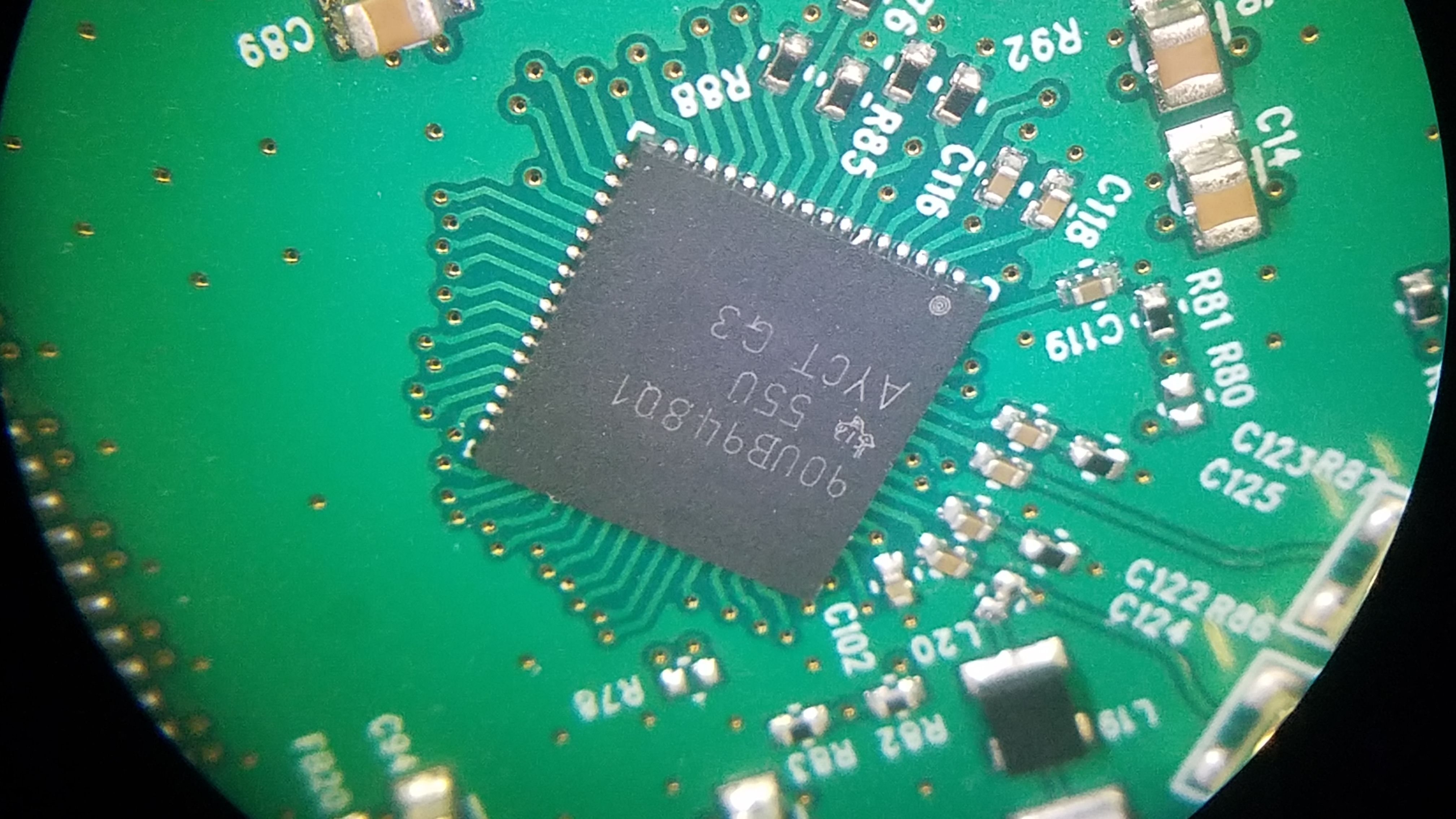
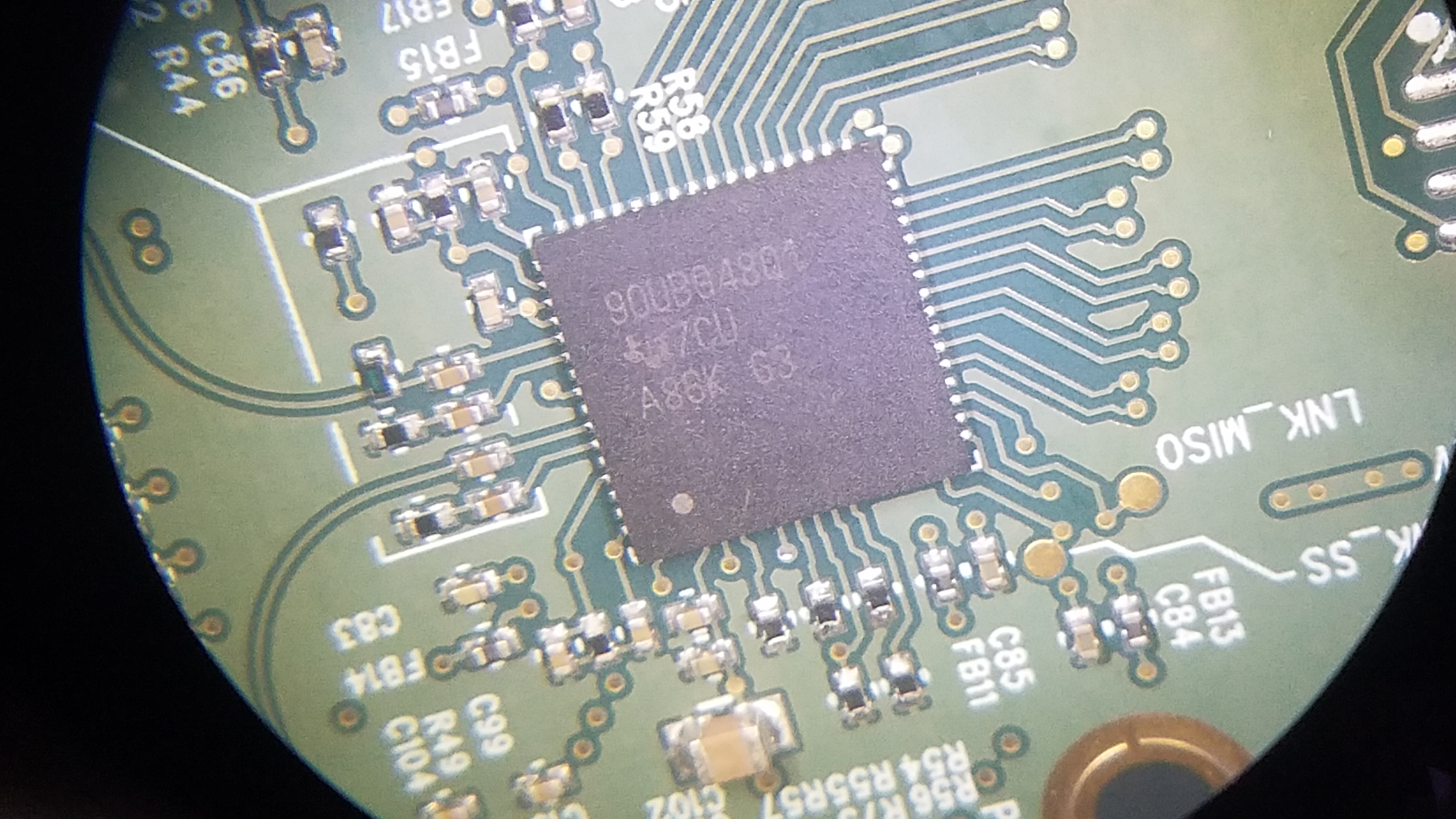
Background: We have a successful pair of boards using 947/948's. Now, we spun the 948 deserializer card to migrate from an ARM M3 to a newer M4. We also changed the connector to a D-Sub coax. The previous version was also coax. But, it used a MIL style coax in a circular connector. We don't think our current issue is the connector. Just want to mention all differences, just in case. While generating the schematics, I literally copied most circuits surrounding the 948 and pasted them into the new design. But, it is a new layout. We are testing with known good 947 serializer cards that work fine with the previous ARM M3 design. We also have EVM cards.

Issue: We are seeing a large number, as many as 65000 in a few minutes, back channel CRC errors. Resorting to verifying the link using BIST, we seem to see fewer, typically 20 to 100 in 10 seconds to 60 seconds of BIST. We suspect those may be CRC errors just prior or after BIST while we're reading the registers. Since, far end registers are unavailable during BIST (so it seems). We don't see forward channel (BIST) errors very often. But, they do occasionally show up in BIST. We have tried various cable lengths. My current test rig has been shortened down to 18" of coax.

The 948 chips in this batch on the newly developed card are much newer than previous batches. We also noticed the data sheet has had some changes since 2014, the one we used for the original design. Latest is Nov 2018. The new datasheet is better. But, nothing really new that we didn't already learn, sometimes the hard way, jumped out at us. 

Questions: Is there any chance new 948 devices might have issues working with old 947 date code parts? Or, is there a new or changed register setting we should know about? (I have to ask.)

Do you have suggestions how to further analyze or diagnose this issue?

Thanks,

Howard

  • Hi Howard,
    This sounds like a signal integrity issue with new layout connector. You should only enable BIST from the 948 side. Can you monitor 948 register Register 0x3B? Poll this register during operation. What is this value and is it changing over time.
  • Hi Darryl,
    Thank-you for the reply. Good idea to monitor 0X3B equalizer status. With what we are testing now, it is not changing. We’ll keep an eye on it. That should tell us something about forward errors or signal integrity, if they reappear.

    Meanwhile, I should provide an update:

    We also considered the new connector. So, to eliminate the new connector, we performed surgery to the PCB, shortened the traces and installed a pair of SMD MMCX connectors. We no longer get any forward channel errors. I’ve run BIST for 12 hours with zero FC errors. However, we still get plenty of BC errors. The 8 bit BC CRC error register overflows in 200 to 400ms during BIST. The 16 bit BC CRC error register overflows in about 6 seconds. In order to get 947 info, we are retrying i2c reads from the 948 to the 947 multiply times in software until we get a successful read of 947 registers from the 948.

    We are still not sure about the new connector scheme. So far, we had to cobble together the D-SUB version due to a lack of proper contacts from two different manufactures. Proper contacts are due in a couple days. When they arrive, we plan to perform network analyzer S-parameter measurements. In the meantime, we’ve eliminated the new connector scheme with very close well placed MMCX connectors. As mentioned, this has eliminated all FC errors. BC errors remain the same, a lot.

    We sync’d up our software between design #1 (the working version) and design #2 (the one with BC errors). Both now have identical register settings and perform BIST identically. Except, design #2 sees BC errors. We did this to confirm software is not responsible.

    Design #2 does not support audio. In removing audio, a difference between #1 and #2, I failed to add pull-down resistors as mentioned in the datasheet to the i2s pins, whoops. So, we added those. That made no difference.

    We’ve been using 33nF/15nF for the channel AC coupling caps. I noticed the new Nov2018 datasheet allows a range. So, we tried 100nF/47nF. That made no difference. BC errors are the same.

    Considering power supply noise as a cause; Design #2 has a TI TPS54561 main supply. In comparison, design #1 uses an LM36002 for main power. To eliminate switching noise from main power, we disabled main power and injected power from an off board linear supply. This made no difference. The POL (point-of-load) supplies are identical between the designs. We may try also eliminating those later. That requires a few more modifications.

    Whenever SMPS is present, there is some noise. Examining noise using a scope, both designs appear okay.

    I noticed the EVMs are using 120 ohm @100Mhz 25mohm DCR ferrites for 1.2V power filtering. I choose 1K @100Mhz 470mohm DCR. I also saw a small amount of IR voltage drop, 20 to 40mV. So, I changed those out to be equivalent to the EVM example. IR drop went away. Yet, BC errors remain the same.

    We have at least one decoupling cap at every power pin. To the EVM’s credit, I notice the EVM tries to have two in many cases. So, we double stacked, added, a 1uF 0402 on top of our 0.1uF caps. We also have other 1uF and 10uF caps nearby. The additional caps made no difference. BC errors remain present.

    We found one old date code part in our inventory. We are installing that on a new design #2 PBCA. We are also installing one of the new date code devices on an old design #1 PCBA. We expect to test those tomorrow, if the manual rework of the PCBAs goes okay.

    More suggestions are welcome.

    Question: If we power the 948 and hold PDB low, will the internal 100/50 ohm termination be present? Will the device in this state be quiet and allow us to perform 50 ohm terminated coax S-parameter analysis?

    Thanks
  • Darryl,
    Sorry. Maybe I haven’t answered your question, “What is this value and is it changing over time?” Deserializer register 0x3B is 0x00. It does not change. The other equalizer settings are default, adaptive. We are currently only using 2 meters of RG316. We will be testing other lengths later, after we get this working better. I don’t believe the equalizer affects the back channel.
    Thanks
  • Hi Howard,

    Thanks for all the details! This should make the debug process go quicker.
    In answer to your question about holding PDB LOW, yes the 100 ohm termination across RIN0/1/+/- will still be there.
    Some basic questions:
    On the 947 did you measure the VDD11, VDD18, and VDDIO are within min/max specs? Are there any overshoot/undershoot?
    On the 948 did you measure the VDD12, VDD33, and VDDIO are within min/max specs? Are there any overshoot/undershoot?
    Did you verify LOCK on the 948 is HIGH with an oscilloscope?
    What 947 OLDI PCLK frequency are you using?
    Is the 948 using the default back channel rate (5 Mbps) or is it at maximum (20 Mbps)?
    Is the 947 in single OLDI input or dual? Are you forcing this mode or auto detecting?
    Is the 947 in single FPD3 ouput or dual? Are you forcing this mode or auto detecting?
    Is the 948 in single OLDI ouput or dual? Are you forcing this mode or auto detecting?
  • Hi Darryl,

    Q&A:

    On the 947 did you measure the VDD11, VDD18, and VDDIO are within min/max specs? A: Yes.

    Are there any overshoot/undershoot? A; No.

    On the 948 did you measure the VDD12, VDD33, and VDDIO are within min/max specs? A; Yes.

    Are there any overshoot/undershoot? A; No.

    The POL power is Intel/Enpirion modules. We use these in numerous other designs. These are well characterized. None the less, since you mention this, we will keep a close eye on these parameters.

    Did you verify LOCK on the 948 is HIGH with an oscilloscope? A: On the scope, plus LOCK and PASS drive transistors that drive LEDs. So, we and users can monitor LOCK all the time.

    What 947 OLDI PCLK frequency are you using? A: Depends. Right now we are just running bare bones test software that performs BIST. PCLK comes from an FPGA. In current BIST testing, PCLK is idle. In operational software PCLK can be between 30 to 150 Mhz depending upon attached LCD panel.

    Is the 948 using the default back channel rate (5 Mbps) or is it at maximum (20 Mbps)? A: We program 0x43 HSCC_CONTROL to 0x07 for HS reverse channel SPI mode. Then we program 0x23 RX_MODE_STATUS to 38. This appears to cause BC to operate at 20 Mbps, observed on the scope.

    Is the 947 in single OLDI input or dual? Are you forcing this mode or auto detecting? A: I believe due to strapping, 947 register 0x4f is 0x00. In current BIST testing, it is single due to no PCLK present. Register 0x5a Daul_Status is 0x92, I believe it is “auto detecting”. We don’t set this register. The 947 end is running production software. For now, I’m running test code on the 948 end.

    Is the 947 in single FPD3 output or dual? Are you forcing this mode or auto detecting? A: Pretty sure this is auto. FPD3 output is currently single, no PCLK. With PCBA design #2 we have not been able to generate a PCLK with existing software. The 948 end is supposed to send some information to the FPGA SOC letting it know how to generate OLDI clock and data. But, the BC has been so bad those packets of information fail. As such, the FPGA SOC does not generate any OLDI. The test code I’m using for BIST doesn’t even attempt to send BC information. Originally we discovered the BC CRC errors when we had logic analyzers hooked up to both ends of SPI, 948 and 947 ends. We saw corrupted SPI transactions. This caused us to backup and resort to testing, especially BIST.

    Is the 948 in single OLDI output or dual? Are you forcing this mode or auto detecting? A: We are setting 0x34 DUAL_RX_CTL to 0x41, RX_LOCK and auto detect. Register 0x49 FPD_TX_MODE is 0x00 at the end of BIST. We do not set this register.

    Thanks

  • Update:

    We’ve been focusing our testing with an assembly that has been modified to have MMCX connectors very close to the 948. The 947 end(s) already have MMCX connectors close to the device. Testing with MMCX connectors yields no FC, forward channel, errors. BC, back channel, errors persist.

    A couple days ago we finally received proper coax contacts for the D-SUB. Testing 12 different 948 assemblies with proper contracts has eliminated all FC errors on all assemblies. This is no surprise, as mentioned earlier, the previous improvised D-SUB connection was questionable. We worked around that by only testing with MMCX until now. We believe the D-SUB connection signal quality is now good. We will be performing some more validation, as well. Meanwhile,

    All 12 assemblies of the tested assemblies, plus the one modified to MMCX, do not exhibit any FC errors. However, all of them encounter both BIST and non-BIST BC CRC errors at very high rates.

    Mentioned in our Mar 6th post, we had one chip in our inventory leftover from an earlier build of boards. So, we removed a 948 from one of the failing boards and installed the older 948. Result: The board is nearly perfect, statistically 10,000X better!

    The 948 device date coded “55U” encounters less than one BC CRC error every 7 minutes while running BIST. Of course, we’d like to see zero. During none BIST operation, we see zero to 2 BC CRC errors only when changing the BC from 5Mbps to 20 Mbps. I believe this is normal when changing BC speed.

    All the 948 devices date code “7CU” encounter excessive BC CRC errors where the BIST error counter typically overflows in 400ms or less. Whereas, the “55U” date code part encounters less than 100 errors in a lengthy 14 to 16 hour BIST tests. There is clearly something different with the newer date code parts.

    We have been questioned about our power rails. We are monitoring these, checking levels and looking for any noise. So far, we have not found anything out of spec or abnormal. We continue to investigate.

    Questions: How is BC data encoded? It appears to possibly be Manchester encoded. Is that correct?

    Have there been any changes to the 948 die between 55U and 7CU?

    Suggestions are welcome?

  • Thanks for the update.
    Correct, the BC is Manchester encoded.
    There hasn't been any changes on the 948 that I am aware of but we do update the screening test program from time to time.
    I will ask our Product Engineer if there is a difference between data codes.
  • Hi Howard,
    My Product person asked if you could provide the full top mark information on both the old and new parts so we can track down to the wafer level.
  • Hi Darryl,

    Attached are pictures of the devices.

    We have one lot code from 55U. There are two lot codes from 7CU.

  • Hi Howard,
    I got the schematic through Kevin Lai. I wasn't aware that you had a PoC network on one channel. Can you remove R43 (1.00K) and L12 (900NH)?
  • Hi Darryl,

    Removing L12 and R43 was one of the first things we tried weeks ago. To make sure, I retested again today with those components and the same components removed on the far end, 947. BIST testing yielded same results, same BC errors.

    Other testing we performed in the past few days:

    We removed another 948 dated 55U from an earlier board. We installed it onto a failing board that had a 7CU dated part. It works. Now we have two working boards with parts dated 55U on design #2 boards.

    Trying to explore everything we might be doing on our side that might be causing errors, using a board that still contains a 7CU dated part, I did the following:
    - Performed numerous measurements and experiments attempting to correlate PSU noise with errors. I could not find any significant observations. (I did this several times earlier. This time I tried a more measured approach.)
    - Taking it a step further I disabled all the SMPS power supplies. Used low noise precision bench power for all the rails. Got the bench power to sequence up properly. This yielded a quieter board. But, it did not improve the performance. Error rate remained the same.
    - Using precision bench power allowed me to try power margining. I tired various levels within the datasheet specifications and some just outside, above and below. Result, no noticeable error rate difference.

    Even though, we have pretty much eliminated software. I regression tested 300-424 boards containing 7CU parts with our latest software. That yielded the same results, lots of errors. When I swap in a board with a 55U date, no other changes, passes.

    We are looking for more 948 devices to test. The 7CU (DEC2017) dated parts were acquired in January 2019 from DigiKey. I’ve emailed them to open up a case, as suggested by Kevin. So far, they have not responded.

    Have you heard anything back from your product person?
  • Hi Howard,
    Thanks for the updated information.
    The Product person is still looking into it.
    Yes, I emailed Kevin to do that.