This thread has been locked.

If you have a related question, please click the "Ask a related question" button in the top right corner. The newly created question will be automatically linked to this question.

DS90UB953-Q1: DS90UB953-Q1 with DS90UB954-Q1 Synchronous Mode setting & DS90UB953-Q1 side CLK_OUT(24MHz) setting issue

Part Number: DS90UB953-Q1
Other Parts Discussed in Thread: DS90UB954-Q1

Hi TI

As following block diagram

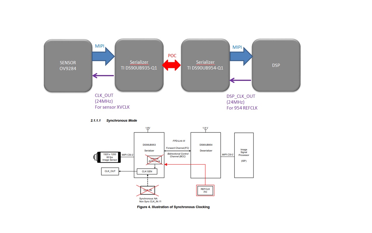
DSP will provide REFCLK 24MHz for DS90UB954-Q1

At synchronous mode :

  1. How do we set Synchronous Mode register for 954 &953?
  2. At synchronous mode, how do we set 953 side CLK_OUT (24MHz) registers?

Best Regards

  • Hello David,

    1) you need to do that by starping through the MODE pins.

    See 954 d/s table 2. If you want to use registers, then you need to set reg 0x58[2:0]=110, and reg 0x6D[1:0]=00.

    and 953 d/s table 7-8. Using registers, Also set reg 0x03[4]=1, and [2:0]=000


    2) you do not need to do any thing. This will be done using default register settings if you use Synch. Mode.

  • HI Hamzeh

    We try this setting

    954

    1:)0x58 set 0xDE the lock was unstable. Do you have other suggestion register setting?

    2:)In that case, we changed our setting to 0x58 0xDD and lock will be stable.

    However, 953's CLK_OUT output changed to 12MHz,

    Our demand is 24MHz, how do we set up our setting?

    Regards,

  • Hello David,

    in reg 0x58 you should have 0x5E for using Synch. Mode. Also make sure you have reg 0x6D[1:0]=00.

    When you change 0x58[2:0] from 110 to 101, you are changing the BC speed from 50Mbps to 25Mbps, which is not a valid use case. Also having a stable LOCK using this BC speed means your link quality is not good enough.

    Please double check your routing and PoC filter components.

    If you send me your schematics for both devices (953, 954) I can check them and tell you if I see any potentional issue.

  • Hi Hamzeh

    updata design file block with 953/954 schematic & layout block (PDF file)

    in this case issue

    1:)954 : 0x58 set to 0xDE / 0x6D set to 0x7C

    the lock status will be unstable, this issue maybe comes from that POC filter can not cover Synch. Mode.

    so we change 0x58 setting to 0XDD , use 953 side PGEN_CFG output color bar to 954.

    954 to DSP can display the color bar image,so in non-Synch. Mode. the POC filter works fine.

    CAM System Block.pdf

  • Hello David,

    please use 0x58=0x5E for 4G operation. You should not set high bits 6 & 7 at the same time. You should be using only Pass-Through, not Pass-Through All.

    Regarding you provided document,

    you may have some issues sue to the fact that you do not have good clearance between your HS trace including TP1 and GND. Same thing applies to the 3x FB on your PoC. These clearance problem could be the reason why you see some instability when using 50Mbps on BC.

    When using Non-Sync, the back channel is running at 10Mbps.

    On 953 PDB pin, please change the C from 4.7uF to 10uF.


    On the 954 side, it is not clear what is the value of the used inductor on PoC! Is it 100uH?

    Are you using Single ended or differential pair at RIN0?

    On 954 PDB pin, please change the R from 33K to 10K, and the C from 4.7uF to 10uF.

    On the 954 layout, you have the same clearance to GND issue.


    Question; while using Non-Sync mode, what is the value of the used Osc on the 953?