This thread has been locked.

If you have a related question, please click the "Ask a related question" button in the top right corner. The newly created question will be automatically linked to this question.

THVD8000: THVD8000 interfacing

Part Number: THVD8000

Dear Hao,

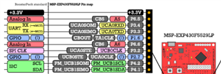
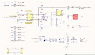
when interfacing THVD8000 to MSP430 UART interface, the R should be connected to UART_TX and the D to UART_RX is that correct?

Do we need pull-up or pull- down resistors on D and R pins?

And also in the THVD8000EVM there is a 15of on R and 50Ohm + 10kOhm pull-down on D pin , what is thee need 15pf and 50ohm components?

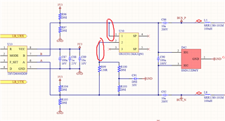
What is the purpose of the 15k and 12k4 resistors on B and A pins?

Best Regards,

David.

  • David,

    The R should be connected to UART RX (to MCU), pin 3, the D to UART TX (from MCU). BTW, the THVD8000 EVM has the connectors for MSP430 launchpad.

    Some people use pull-up on R, which is optional.

    The 15pF on R is for test purpose, which could be used for noise filtering with different value too.

    The 50Ohm on D could be used to match the signal generator's impedance.

    The 15kOhm on A/B pins are for debug. The 120Ohm is the termination for signal integrity. Other than the termination, most of other components are not necessary.

  • Hi Hao,

    thank you for the info. Can you just tell there is a 10k pull-down on the D line is it mandatory?

    Also is it possible to provide the BOM and Layout of the THVD8000EVM for reference?

    Best Regards,

    David.

  • David,

    For the BOM and layout, it would be easier to email myself or Hao directly. It's much easier to share that information through email than on E2E.

    Regards,

    Eric Hackett 

  • David,

    The 10k pull-down on the D is not mandatory. You can find the gerber file in this thread. I also upload the BOM for your reference.

    INT122A(001)_BOM.XLS

  • Dear Hao,

    can you tell is it possible to get the altium layout files?

    Also can you tell the A  and B track does it need to be 120Ohm diff ref to GND?

    Best Regards,

    David.

  • David,

    There's an email thread about the THVD8000EVM Altium files, where we can handle that there and leave it offline.

    The 120 ohms is meant to match the characteristic impedance of the twisted-pair cabling typically used in these applications, and to create an overall impedance of 60 ohms, to be close to the RS485 driver requirement.

    Regards,

    Eric Hackett 

  • Dear Eric,

    Thank you for the replay

    1) if 120Ohm twisted pair is used then:

    What is the impedance on your demo board for lines

    1a) from U6 to R11/R9 (B and A lines), single ended and differential impedance? ( track width is 10mil spacing 15.6mil)

    1b) from R11/ R9 to C11/C9 (B and A lines), single ended and differential impedance?  ( track width is 30mil spacing 45.26mil)

    1c) from C11/C9 to J27 ( B_LC and A_LC lines) , single ended and differential impedance?  ( track width is 60mil spacing 210mil)

    2)is it ok to reference the A/b lies and B_LC/A_LC lines to the same GND?

    3) Regarding the jumper that turns on termination on last slave. is it ok to use a switch on the edge of a PCB and then have long lines ( 1500mils) to the termination resistor? Marked in red on picture below

    Best Regards,

    David.

  • David,

    1) 120Ohm matches the differential cable/pcb impedance (or 60Ohm single-ended).

    1a) this trace is between the IC and termination and should be low impedance;

    1b) 1c) these routing should match the cable impedance;

    Given the application with long cable, usually the pcb trace is not the dominant factor of signal quality. In your design, you can put the IC as close as to the connector.

    2) the DC voltage at the two sides of the decoupling capacitor (C9/C11) are isolated. They don't share the same ground.

    3) I think it's OK to do so. However I would make the jumper routing as short as possible, otherwise you could create some open-ended 'stubs' on the bus.

    For impedance matching, this app note is a good resource. For stub, please refer to section 3 of this technical note.

  • Dear Hao,

    I looked at the THVD8000EVM  board in altium and:

    1) Regarding impedances 

    if i put the numbers from board ( trace width/separation and stack-up details) in the impedance calculator i get

    1a) for A/B track 60OHm single ended and 111Ohm differential impedance ( referenced to L2)

    1b) for A/B track after R10-R11/R8-R9 - 31ohm single ended  and 62ohm differential  ( referenced to L2) -> this don't match 120Ohm diff impedance of ta cable ?

    1c) for A_LC/B_LC track after C9/C11 - 18ohm single ended  and 37Ohm differential   ( referenced to L2) -> this don't match 120Ohm diff impedance of ta cable ?

    2) On the whole second layer is the same GND plane, and you sad that the A/B lines and A_LC/B_LC don't share the same GND? 

    Best Regards,

    David.

  • David,

    Thanks for looking into this.

    1) the EVM was not designed to match the cable impedance. Again compared to 10s- to 100s-meter cable, the PCB trace is negligible. However you're welcome to make the trace impedance matching in your design.

    2) the A/B line is grounded to GND, and A_LC/B_LC is to GNB. The purpose of power line communication is to transmit AC signal and block DC.

  • Dear Hao,

    please can you check my schematic, and tell if some of the components can be removed or need to be replaced?

    Also can you tell in my design:

    1) is it ok to reference B and A signal to GND? And use 60Ohm single ended and 120Ohm diff impedance?

    2) is it ok to reference BUS_P and BUS_N signal to GND or need to reference to BUS_GND? Also is it ok to use 60Ohm single ended and 120Ohm diff impedance?

    Best Regards,

    David.

  • David,

    Is the power 48V DC? 1) yes, please reference A/B to GND. 2) please reference BUS_N and BUS_P to BUS_GND. Either 60Ohm single-ended or 120Ohm differential works.

  • Hao,

    yes the power is 48V DC , why are you asking?

    Br.

  • No worries. I saw SMA6J48A is used on the power rail.