This thread has been locked.

If you have a related question, please click the "Ask a related question" button in the top right corner. The newly created question will be automatically linked to this question.

Linux/DS90UB954-Q1: DS90UB954A

Part Number: DS90UB954-Q1

Tool/software: Linux

Hi all,

       Our product use 954 to receive images from 913(720p) and 953(1080p).  One or two bad images will be received in 954 side after switch from RIN1(720P) to RIN0(1080P).

When 954 switch from RIN0 to RIN1, there is no such issue.

Architecture used as belows:

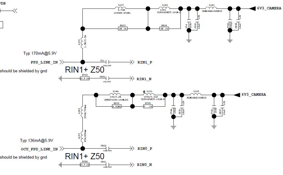
T         T  --------------RIN0-----------------913-------(720P@30fps yuv422)

 |  954 |

 |_     _| -----------------RIN1-----------------953-------(1080P@60fps yuv422)

      The bad image looks like some pixel lines  shifted or some pixel lines turns  green. The bad images will be replaced by incoming right images quickly.

  In 954 side  could detect RX_PORT_STS1(0x4D) == 0x33, Bi-directional Control Channel CRC Error Detected, when this happens.

Any advices ?  we need

thanks a lot 

  • Hi,
    for the input port switching, as they have diff. data rate, the UB954 should take little time to relock it, so there are some errors here.
    also, the back channel rate could be different when UB954 is paired with UB953 and UB913a, how do you match it? also, TO pair with the UB913a and UB953, UB954 should have diff. setting, all these variation could result into output abnormal during switching.


    regards,
    Steven
  • Hi Steven,

    Thanks for your support, and more information supplement:

    1. After input port switching(RIN1 to RIN0), UB954 reserve 500ms for relocking. 

    2. Register 0x58[2:0] = 110b  is used for the back channel rate.  —— 50 Mbps (default for DS90UB953 CSI Synchronous back channel compatibility)3

    3. Settings used in UB954 as bellow:

    //1920x1080@60fps
    static struct regval_list ds90ub954_regs_channel0[] = {
        {0x33, 0x01}, //open csi0, 4lanes
        {0x4C, 0x01}, //TODO just port RX0 enable 0x01
        {0x6D, 0x74}, //csi-2
        {0x20, 0x20}, //TODO fwd enable RX0 0x20
        {0x0C, 0x85}, //TODO Port 0 Receiver Pass, Port 0 Receiver Lock, Enable Port 0 Receiver. 0x85
        {0x1F, 0x02}, //PLL 800Mbps
        {0x58, 0xDE}, //enable pass throu 500MBps                                                                                                                                                                                          
        {0x5C, 0xB0}, //SER_ALIAS_ID 8bit 0xB0
        {0x5D, 0x34}, //slaveAliase[0] 8bit 0x34
        {0x65, 0x34}, //slaveAliase[0] 8bit 0x34
        {0x70, 0x1E}, //yuv422
        {0x7C, 0xC0},
        {REG_DLY, 0xC8}, //delay 200ms
        {REG_DLY, 0xC8}, //delay 200ms
        {REG_DLY, 0x64}, //delay 100ms
    };

    //1280x720@30fps
    static struct regval_list ds90ub954_regs_channel1[] = {
        {0x33, 0x01}, //open csi0, 4lanes
        {0x4C, 0x12}, //TODO just port RX0 enable 0x01
        {0x6D, 0x7F}, //coax
        {0x20, 0x10}, //TODO fwd enable RX0 0x20
        {0x0C, 0x96}, //TODO Port 0 Receiver Pass, Port 0 Receiver Lock, Enable Port 0 Receiver. 0x85
        {0x1F, 0x03}, //PLL 400Mbps
        {0x58, 0x78}, //enable pass throu
        {0x5C, 0xB0}, //SER_ALIAS_ID 8bit 0xB0
        {0x5D, 0x34}, //slaveAliase[0] 8bit 0x34
        {0x65, 0x34}, //slaveAliase[0] 8bit 0x34
        {0x70, 0x1E}, //yuv422
        {0x7C, 0xC0},
        {REG_DLY, 0x0A}, //delay 10ms
    };

    Best Regards,

    Luke

  • Hi Steven,

    Thanks for your support, and more details supplement:
    1. After input port switching(RIN1 to RIN0), UB954 reserve 500ms for relocking.
    2. Register 0x58[2:0] = 110b is used for the back channel rate. —— 50 Mbps (default for DS90UB953 CSI Synchronous back channel compatibility)
    3. Settings used in UB954 as bellow:

    //1920x1080@60fps
    static struct regval_list ds90ub954_regs_channel0[] = {
    {0x33, 0x01}, //open csi0, 4lanes
    {0x4C, 0x01}, //TODO just port RX0 enable 0x01
    {0x6D, 0x74}, //csi-2
    {0x20, 0x20}, //TODO fwd enable RX0 0x20
    {0x0C, 0x85}, //TODO Port 0 Receiver Pass, Port 0 Receiver Lock, Enable Port 0 Receiver. 0x85
    {0x1F, 0x02}, //PLL 800Mbps
    {0x58, 0xDE}, //enable pass throu 500MBps
    {0x5C, 0xB0}, //SER_ALIAS_ID 8bit 0xB0
    {0x5D, 0x34}, //slaveAliase[0] 8bit 0x34
    {0x65, 0x34}, //slaveAliase[0] 8bit 0x34
    {0x70, 0x1E}, //yuv422
    {0x7C, 0xC0},
    {REG_DLY, 0xC8}, //delay 200ms
    {REG_DLY, 0xC8}, //delay 200ms
    {REG_DLY, 0x64}, //delay 100ms
    };

    //1280x720@30fps
    static struct regval_list ds90ub954_regs_channel1[] = {
    {0x33, 0x01}, //open csi0, 4lanes
    {0x4C, 0x12}, //TODO just port RX0 enable 0x01
    {0x6D, 0x7F}, //coax
    {0x20, 0x10}, //TODO fwd enable RX0 0x20
    {0x0C, 0x96}, //TODO Port 0 Receiver Pass, Port 0 Receiver Lock, Enable Port 0 Receiver. 0x85
    {0x1F, 0x03}, //PLL 400Mbps
    {0x58, 0x78}, //enable pass throu
    {0x5C, 0xB0}, //SER_ALIAS_ID 8bit 0xB0
    {0x5D, 0x34}, //slaveAliase[0] 8bit 0x34
    {0x65, 0x34}, //slaveAliase[0] 8bit 0x34
    {0x70, 0x1E}, //yuv422
    {0x7C, 0xC0},
    {REG_DLY, 0x0A}, //delay 10ms
    };

    Best Regards,

    Luke
  • Luke,
    the 1 or 2 bad images is reported just after the switching from ub953 to UB913 or from UB913 to UB953?
    can you reset the UB954 after switching? Some last frame data would be restored into the line buffer.

    btw, how do you check the 1 or 2 bad image?

    best regards,
    Steven
  • Hi Steven,

    1. It happens when switching from UB913 to UB953.(UB913 is used for transferring 720p images @30fps  and UB953 for 1080p images@60fps)

    it works fine when switching from UB953 to UB913.

    2. Reset UB954  after switching we also have tried, but it doesn't work.  With reset operation, it  seems to be more easier to get bad images.

    3. After UB954 receive image,  system render it to screen as soon as possible. When bad image received, we could identify it by human eyes.

    Best Regards,

    Luke.Lan

  • If keep the UB954 is connected to UB913, does it have bad images?
    also, the issue happened just after the switching? After run a while, it has no any issue?

    From the chip design, if you reset the UB954 after the switching, the link should be stable! so pls identity it is chip switching issue or system switching issue.


    best regards,
    Steven
  • Hi Steven,

    If keep the UB954 is connected to UB913, no bad images will be received. it works fine.
    Issue happened just after the switching, bad image comes after switching a little while( about 1s after).
    And then no more bad images will received.

    "Bi-directional Control Channel CRC Error" is pair with the bad image showing up. So I more likely to believe it is
    chip switching issue. And we will try add reset operation back after switching op, and make more contrast.

    Best Regards,
    Luke.Lan
  • I don't think this is switching issue, I think it is your board setting issue. please below analysis:
    1. the issue is reported after 1s, the IC chip response time is so slow?
    2. for the setting, i check your reg., when paired with UB913a, the csi2 port lane rate is 400Mbps, you should refer to page40 of UB954 to set the correct CSI2 port timing. question: why not keep the same CSI2 port lane rate for both ub953 and UB913?
    3. if you have reset after the power-on, and have ~100ms delay, the link is becoming more robust. after reset, you should re-config the reg.
    4. does it have other noise generation in the board after the switching? which could result into CRC error.
    5. what is the PoC network design of UB954? which could result into CRC error.

    best rgds,
    Steven
  • Hi Steven,

    1. Keeping same  port lane rate for both ub953 and UB913,  issue still cannot be resolved.  But it seems a little better than before.

        And ub953 use "coax cable mode-CSI Mode" and ub913 use "coax cable mode-Raw 10 Mode", which could not be change(we tried).

    2. Replaced with bigger diameter coax cable(the best we can find),  bad images received will not be as frequency as before but still exits.

    3. Our PoC design refers to the official document.(as attachment).  Hope you can help us review again.

    Best regards,

    Luke

    new  settings:

    ```

    //1920x1080@60fps                 
    static struct regval_list ds90ub954_regs_channel0[] = {
        {0x01, 0x02}, //reset all
        {REG_DLY, 0x64}, //delay 100ms
        {0x33, 0x01}, //open csi0, 4lanes
        {0x4C, 0x01}, //TODO just port RX0 enable 0x01
        {0x6D, 0x74}, //coax csi  
        {0x20, 0x20}, //TODO fwd enable RX0 0x20
        {0x0C, 0x85}, //TODO Port 0 Receiver Pass, Port 0 Receiver Lock, Enable Port 0 Receiver. 0x85
        {0x1F, 0x02}, //PLL 800Mbps
        {0x58, 0xDE}, //enable pass throu 500MBps
        {0x5C, 0xB0}, //SER_ALIAS_ID 8bit 0xB0
        {0x5D, 0x34}, //slaveAliase[0] 8bit 0x34
        {0x65, 0x34}, //slaveAliase[0] 8bit 0x34
        {0x70, 0x1E}, //yuv422    
        {0x7C, 0xC0},                 
        {REG_DLY, 0xC8}, //delay 200ms
        {REG_DLY, 0xC8}, //delay 200ms
        {REG_DLY, 0x64}, //delay 100ms
    };                                
                                      
    //1280x720@30fps                  
    static struct regval_list ds90ub954_regs_channel1[] = {
        {0x01, 0x02}, //reset all
        {REG_DLY, 0x64}, //delay 100ms
        {0x33, 0x01}, //open csi0, 4lanes
        {0x4C, 0x12}, //TODO just port RX0 enable 0x01
        {0x6D, 0x7F}, //coax raw10                                                                                                                                                                                                         
        {0x20, 0x10}, //TODO fwd enable RX0 0x20
        {0x0C, 0x96}, //TODO Port 0 Receiver Pass, Port 0 Receiver Lock, Enable Port 0 Receiver. 0x85
        {0x1F, 0x02}, //PLL 800Mbps
        {0x58, 0x78}, //enable pass throu
        {0x5C, 0xB0}, //SER_ALIAS_ID 8bit 0xB0
        {0x5D, 0x34}, //slaveAliase[0] 8bit 0x34
        {0x65, 0x34}, //slaveAliase[0] 8bit 0x34
        {0x70, 0x1E}, //yuv422    
        {0x7C, 0xC0},                 
        {REG_DLY, 0x0A}, //delay 10ms
    };                                

    ```

  • 1. of course, the UB913a and UB953's work mode can not be changed. they have diff. working mode when paired with UB954.
    2. if cable has problem, the link error does NOT happen just in 1min. PoC layout and PoC component selection is important.
    3. how do you switch? you drop one camera? from the setting the serializer alias name are same. if both 913a and 953 modules are attached, please use diff. alias name.
    4. for both cases, please set the 0x58 reg. as 0x78 and 0x7E respectively. pass through all is not recommended here.

    regards,
    Steven
  • Hi Steven,

    During switching, ub954 just forwards one input signals(the other one is still power on). And 954 won't configure remote camera, so alias names are both not used. does it matter?
  • sorry, please clarify your issue:
    And 954 won't configure remote camera, so alias names are both not used
    --> why "so alias names are both not used" is got? Do you reset the UB954 after switching?

    Steven
  • why "so alias names are both not used" is got?

    - "so alias names are both not used" what i mean is : remote camera used default setting.  UB954 won't use these alias name to configure remote sensor. And the remote cameras works fine on under default settings. 


    Do you reset the UB954 after switching?

     - Yes, we will reset  UB954.  

  • If both cameras are alive and have same remote slave ID addr., UB954 should send the control signals to both slaves I2C in the two cameras.

    regards,
    Steven