This thread has been locked.

If you have a related question, please click the "Ask a related question" button in the top right corner. The newly created question will be automatically linked to this question.

P82B96: How to place P82B96

Part Number: P82B96
Other Parts Discussed in Thread: LP55231, P82B715, TCA9517

Hi Sirs,

We would like to use P82B96.

May i know how to place P82B96 ? One for master side and one for slave side?

And how many P82B96 we need per board?

Actually our application is like datasheet page 1 Long-Distance I 2C Communications

The fist board is connect cable to second board. And second board is connect cable to third board.

Thanks!!

  • Hi Sirs,

    Update our schematic as below

    Could you help us to double check? 

    Thanks!!

  • Hi,

    thanks for reaching out!

    - The schematic is very useful for me to understand; I can confirm that, after reviewing it, everything looks within the specs of the datasheet and it shouldn't present major issues. Just as a reminder, I would like you to think of how much current goes though the pull up resistors and if they are in parallel with any other resistor from the UART line, because in this case power dissipation could be a problem.

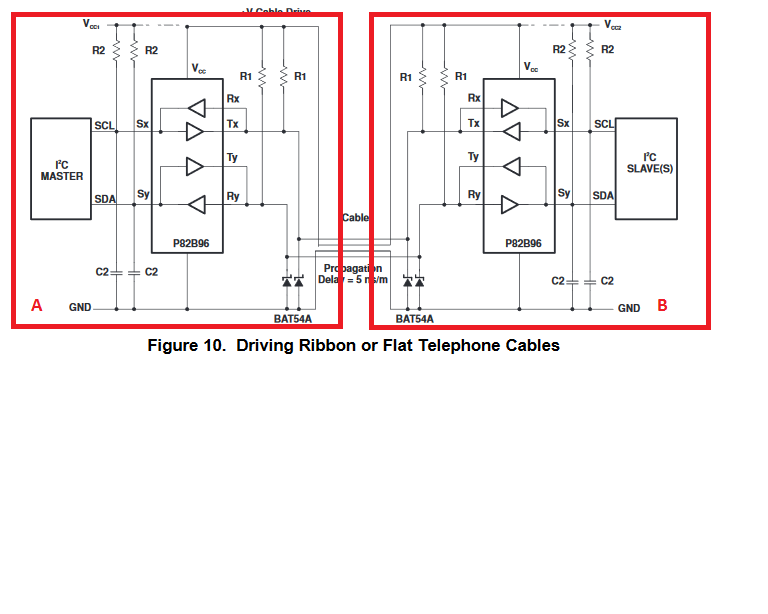
    - For your first question instead I'm not sure I really understand your entire application. If you only have one Master and one Slave then you will need two devices P82B96 as shown in the attached figure 

    Here the two boards will have A, the master and one P82B96, B will have the slave and one P82B96. But in your questions you talk also about a third board and I don't really understand how the whole system looks like.

    Would it be possible for you to send me a high level block diagram of your system? Just so that I can recommend to you the best solution possible.

    Also, how fast the communication will be (frequency), what type of cable are you going to use (ex. CAT5), how long will the cable be? These info will help me to better understand your system and suggest better solutions.

    I hope this helps; I'll wait for your reply in order to come back to you.

    Thank you and best regards,

    Adrian

  • Hey Shu,

    To follow up with Adrian, I want to be sure I am not misinterpreting something. Your schematic references the UART_TXD and UART_RXD. Was that a mistake or are you trying to interface this device with a UART device?

    Are you able to tell us what end equipment/application you are trying to use this P82B96 for?

    Thanks,
    -Bobby
  • Hi Sirs,

    Thanks for quick reply, the red line is our reply. 

    The schematic is very useful for me to understand; I can confirm that, after reviewing it, everything looks within the specs of the datasheet and it shouldn't present major issues. Just as a reminder, I would like you to think of how much current goes though the pull up resistors and if they are in parallel with any other resistor from the UART line, because in this case power dissipation could be a problem.

    Is it OK if we change the pull-up resistor from 330ohm to 1Kohm or higher? Do you have any advice for our application?

    For your question instead I'm not sure I really understand your entire application. If you only have one Master and one Slave then you will need two devices P82B96 as shown in the attached figure

    Here the two boards will have A, the master and one P82B96, B will have the slave and one P82B96. But in your questions you talk also about a third board and I don't really understand how the whole system looks like.

    So, would it be possible for you to send me a high level block diagram of your system? Just so that I can recommend to you the best solution possible.

    Also, how fast the communication will be (frequency), what type of cable are you going to use (ex. CAT5), how long will the cable be? These info will help me to better understand your system and suggest better solutions.

    Please refer to attached roughly block diagram. We will use 400KHz clock frequency if possible.

    P82B96_block_diagram.pdf

    To follow up with Adrian, I want to be sure I am not misinterpreting something. Your schematic references the UART_TXD and UART_RXD. Was that a mistake or are you trying to interface this device with a UART device? 

    We reserved UART circuit for alternative circuit purpose.

    Are you able to tell us what end equipment/application you are trying to use this P82B96 for?

    We would like to use P82B96 to drive 3 LED driver(TI/ LP55231).


  • Hey Shu-Cheng,

    The P82B96 device is meant to sink large amounts of current through long cables. From what you've shown us looks like the cables and distance are not very far. This device is also a bit overkill and could be done through simpler means, I do not think you need this device and could maybe use one of our normal buffers like TCA9517 or TCA980x if the cable capacitance is below 400pF. If you think the total capacitance will exceed this, you could also try out P82B715 device which is similar to the P82B96 but is a bit cheaper and can buffer 3000pF of capacitance.

    "Is it OK if we change the pull-up resistor from 330ohm to 1Kohm or higher? Do you have any advice for our application?"

    -Your pull up resistor will be dependent on how much capacitance you expect to be on the long cables. You can calculate the maximum pull up resistor by using the equation: Rp(max)=t(risemax)/(0.8473xC(cable))

    t(risemax) will be 300ns if you are using 400kHz and 1000ns if you use 100kHz clock.

    You may want to use a smaller resistor to help drive the signal.

    "Please refer to attached roughly block diagram. We will use 400KHz clock frequency if possible."

    -Your set up should work from what I can see.

    "We reserved UART circuit for alternative circuit purpose."

    -This device has a Vol on the Tx/y pins which may or may not work with a Vil of UART. This device is also open drain whereas UART is push pull so you may run into problems.

    If you have any other questions, feel free to ask!

    -Bobby