This thread has been locked.

If you have a related question, please click the "Ask a related question" button in the top right corner. The newly created question will be automatically linked to this question.

iso5500EVM

Other Parts Discussed in Thread: ISO5500EVM, REF2925

Hello,

Does any one has built this IGBT gate driver circuit?

How do I do using the iso5500EVM to drive single 100A, 1200V IR or Ixys IGBT?

Secondary,

For driving a high-power IGBT safely, there is a high carrier frequency modulated into baseband tightly together.

In the iso5500EVM, there is no any information mentioned about it.

Could you please give me mor information for a testing circuit using the iso5500EVM?

Thanks a lot.

  • Hi Richard,

    the ISO5500 data sheet has a circuit example in the application section. Our device can only provide up to 2.5A peak output current for the gate. But we also show a current booster at the end of the data sheet.

    With regards to the pulse-width modulated (PWM) signal please contact our DSP and/or MCU forum which can provide with code examples.

    Please let me know whether this helps. Regards, Thomas

  • Richard, I have attached a circuit example for high-or low-side drive.

    Regards, Thomas

    ISO5500 Single IGBT Drive Circuit.pdf
  • Thanks.

    My concerned question is how to add a high frequency carrier signal to this gate driver.

    One single frequency to a control a high-power IGBT results in a disaster.

  • Richard,

    I'm not sure whether there are PWM controllers with low frequency carriers (i.e. 20kHz), otherwise you would to build a discrete one. Also, as I said, contact our MCU/DSP gurus, who know how to write PWM code and probably have ready code available.

    Regards, Thomas

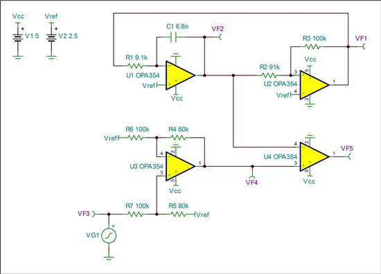
  • Hi Richard, here is a PWM circuit for your needs. You can use a lower cost quad op-amp with rail-to-rail capability though, such as the LM614 (I think)..

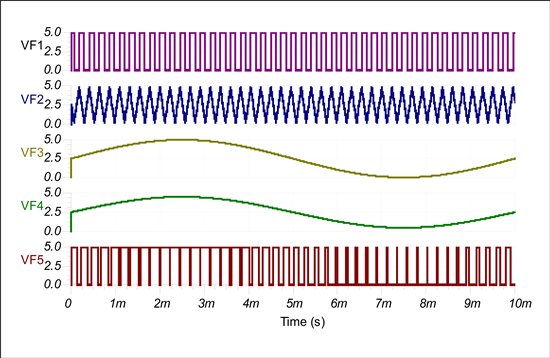
     U1 is configured as an integrator and U2 as a comparator. For good stabiliity use a low-cost 2.5V reference (i.e.REF2925). The comparator hysteresis is given with Vhys = VF1 x R2/R3 and is symmetric around Vref. The upper and lower limit of this hysteresis window determine the switching levels of the comparator. When the comparator output switches it forces the integrator to integrate up- or downwards. Once the integrator output voltage hits the comparator switching levels the comparator output changes. The square wave and the triangular wave are swinging around Vref and close to the supply rails (see waveforms below).

    U4 is also configured as a comparator without hysteresis. Here your analog input voltage is compared to the triangular voltage, thus resulting in the final PWM output. In order to center a single-ended input voltage (referenced to ground) around Vref, I used a difference amplifier (U3) with a gain of 0.8 (G = R4/R6) and biased it with Vref. Its output voltage is given with: VF4 = (VF3 - Vref) x R4/R6 + Vref. This way a 5V input voltage swing is reduced to 4V and centered around the 2.5V reference at the output (again see waveforms below).

    Hope this helps. Regards, Thomas

  • In the RM46L852_instaspin_bldc and RM46L852_sensored_speed_smo projects

    there have 

    void PWM_disableChopping(PWM_Handle pwmHandle);

    void PWM_enableChopping(PWM_Handle pwmHandle);

    void PWM_setChoppingClkFreq(PWM_Handle pwmHandle,const PWM_ChoppingClkFreq_e clkFreq);

    void PWM_setChoppingDutyCycle(PWM_Handle pwmHandle,const PWM_ChoppingDutyCycle_e dutyCycle);

    void PWM_setChoppingPulseWidth(PWM_Handle pwmHandle,const PWM_ChoppingPulseWidth_e pulseWidth);

    totally five PWM_chopping functions declaration and bodies.

    Where can I find about PWM_chopping implementation examples code?

    Thanks.