This thread has been locked.

If you have a related question, please click the "Ask a related question" button in the top right corner. The newly created question will be automatically linked to this question.

TIC12400-Q1: Inquire about reverse voltage protection

Part Number: TIC12400-Q1
Other Parts Discussed in Thread: TIC12400

Hi team. 

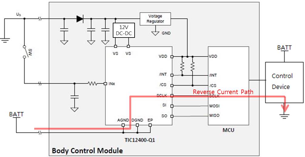
My customer wants to apply the TIC12400-Q1 to a 36V automotive system.

To solve the input voltage range problem, the TIC12400-Q1 power supply will be supplied 12V using dc-dc.

So I want to check if there are any problems below.

1. When the battery is connected in the reverse direction, is there any possibility that a current path can flow to the SPI port through the TIC12400-Q1 internal circuit?(See case1 and case2 below)

    If current can flow, how do you design the damping resistor to protect the SPI port and MCU?

2. In Case 2 below, if the 36V is input with reverse voltage, can the TIC12400-Q1 have a problem?

    (There is no direct current flow from INx to Vs due to the reverse voltage protection diode. There is only the path through the SPI or GPIO port of the MCU and the control unit.)

  - Case 1.

  - Case 2.

Thank you!

  • Hi Charles,

    All the INx pins have internal reverse battery protection. We have this protection mechanism just in case someone jump the car but mis-wire the cable polarity.

    Unfortunately, TIC12400-Q1 cannot tolerate down to -36V reverse battery condition. Here is our absolute max table for your reference. 

  • Hi Fan,

    Thank you for your fast replying.

    Could the current flow through the SPI port to the MCU at case1?

    To prevent reverse current from flowing through Vs, we added a reverse protection diode to the battery input.

    Thank you!
  • Hi Charles, 

    Thanks for pursuing this current backflow question. I did not understand your concern. I assume on your BCM, all grounds are connected as I connected below. 

    In your Case 1, the battery is miswired, while on the right, the control device's power supply is not miswired. In this case, if your control device and BCM sharing ground, yes, current will back-flow to the battery on the left. However, it is not via TIC12400. It is through shared ground pins. I wouldn't consider this case as current backflow. I think it is battery-to-ground short circuity. What do you think?

  • Hi Fan,

    Sorry, the circuit above has some errors.

    I attached the modified schematic, so please check again.

    Please refer to the circuit below and check if the current can flow from the case 1 through the SPI port to the MCU.

    (Please refer to circuit below for Case2 also and check again.)

    Thank you!

  • Hi Fan,
    Please check as soon as possble.
  • Hello Charles,

    In the reverse battery case, the voltage regulator which supplies VDD to the MSDI and MCU is isolated from negative voltage by the external blocking diode. The VS power supply input to MSDI is also isolated from negative voltage by the same external diode. During a reverse battery case, the VS and VDD supplies as well as the board ground will settle to BATT level. Since there is effectively no voltage drop across VS, VDD, and board ground, the MSDI and MCU will be un-powered. This will not cause current flow through the SPI.

    However, I do not know anything about the High Side Switch in the diagram. In a reverse bias case, the GPIO control signal will be at BATT level while the left-side connection is connected to ground. I do not know what that will do to the switch. Also, the ground connection on the Load will most likely also be connected to BATT during a reverse battery case. I am assuming the Load ground is the same as the rest of the chassis ground for the car.

    Therefore, TIC12400-Q1 will not give you trouble in reverse battery, but we are not quite clear about the impact from your high side switch.