This thread has been locked.

If you have a related question, please click the "Ask a related question" button in the top right corner. The newly created question will be automatically linked to this question.

TPS2546: STATUS is kept low even OUT pin is not connected with load

Part Number: TPS2546

hi,

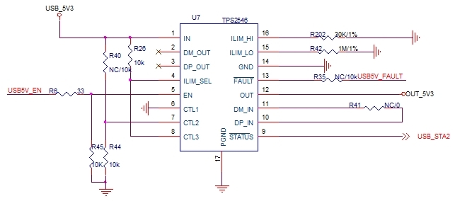
From DS. of tps2546, STATUS pin will keep high  when load current from OUT pin is < 45mA.With attached schematic, both D+/D- pins are float,STATUS pin is pull-up to external 3.3V power rail via 4.7kohm resistor . the STATUS pin is kept low even wehn OUT  pin is floating ( it means that there is no current out of OUT pin). would you like kindly help check any possilbe error with the schematic? and what tests we should to do to find what cause this issue.
  • Hi Ken,

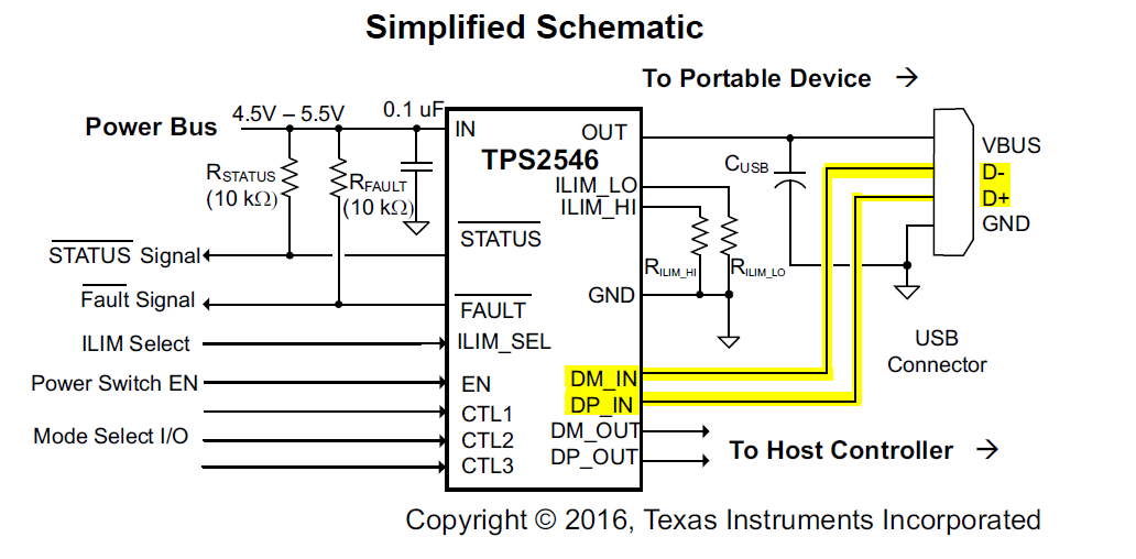
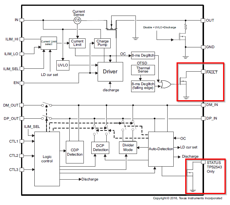
    The first problem that I see is that the D+/D- lines are shorted together as opposed to being connected to the USB connector. These lines need to be connected to the USB connector as this is how the TPS2546 communicates with the portable device connected.  As far as the STATUS and FAULT pins, those need to be connected to a 5V rail. These pins do not drive anything, as they are connected to the source of a FET as shown in the functional block diagram. Make these two changes, and the part should operate as expected.

    If this helped answer your question, please click This resolved my issue

  • HI,

    1.In customer application, there are no D+/D- pins in its portable device.D+/D- is floating, is not shorten together. And in current project, only load detection function and 1.5A current limitation function of tps2546 are planed to be used.  can tps2546 support this requirement?

    2.Can both STATUS pin and FAULT pin be pull-up to other powe rail(3.3V),  a different power rail  with IN power rail(5V), rail via a resitor? now customer connecte STATUS to 3.3V power rail. does it make any error?,

  • Hi Ken,

    1. I didn't see that R35 was a no connect. Still, the point stands that you need to connect the D+ and D- lines from the TPS2546 to the USB connector. The purpose of the STATUS pin is to determine when a portable device has been connected, so that the system can then take the TPS2546 out of low power mode.

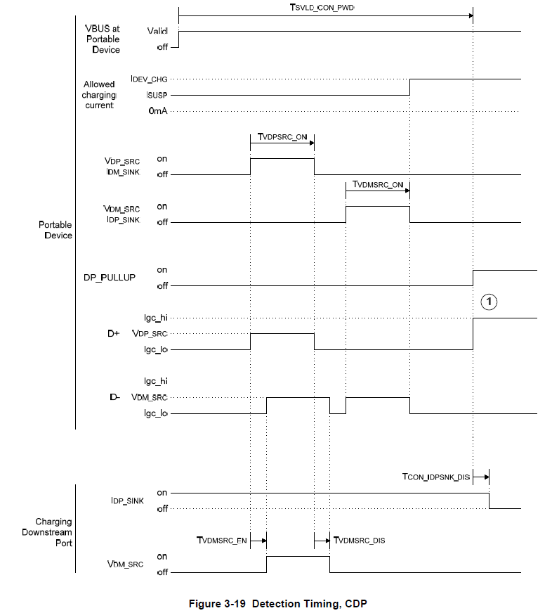
    I’ll give an example for if you are trying to test and verify for CDP mode.  Here's a CDP timing diagram example found within the BC1.2 specification. The portable device starts the conversation by sending a signal on the shared D+ line.  The source device detects this, and sends a response back on the D- line. The Portable device receives this response, and to verify that the D+ and D- lines are not shorted together (DCP mode), it sends another signal back through the D- line. The source device receives this signal through the D- line, but does not send back a response. Since the portable device never received a signal back on the D+ line, it knows that the D+ and D- lines are not shorted together, thus it is in CDP mode.

    If you do not connect the D+ and D- lines to the TPS2546, it will not be able to receive or send back a response signal, so the portable device will assume it is in SDP mode, and only charge at 500mA instead of 1.5A

    2. I would not recommend doing that. I would recommend connecting STATUS and FAULT to the power path via  10k resistor as shown in the first picture of my original response.

    Let me know if this makes sense or if you have any other questions. If this answer your question please click This resolved my issue