This thread has been locked.

If you have a related question, please click the "Ask a related question" button in the top right corner. The newly created question will be automatically linked to this question.

LSF0204D: Gound shifting at low voltage site (3v3)

Part Number: LSF0204D

Hello,

I used LSF0204D for converting SPI Signal from 3v3-to-5V

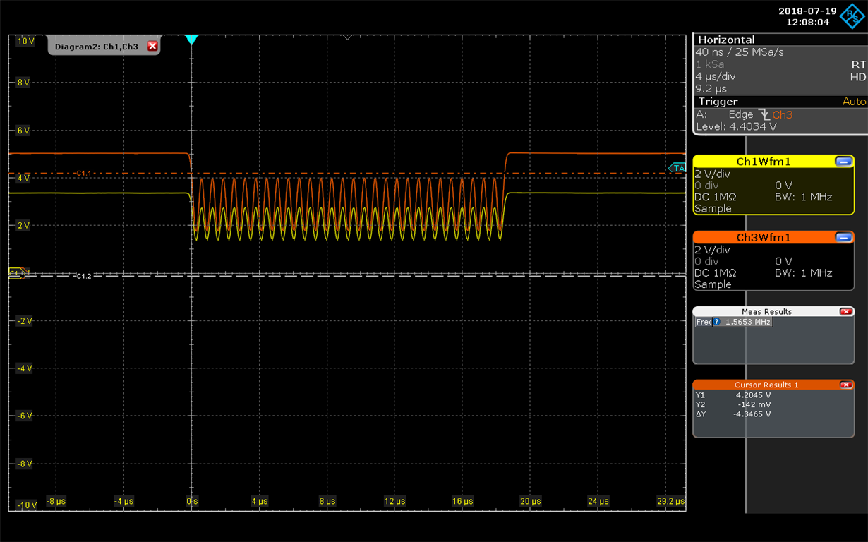
1) The MOSI signal which generated by µC give a clear and good quality at 3v3 level ( High = 3v3, Low = 0V). But if i connect the MISO-singal to LSF0204D, the Low-Level is shift to about 0v8 and therefore the output at 5V is also shift too (High = 5V, low = 1V) -> how can i have clear 0V at Low-Level at both sites?

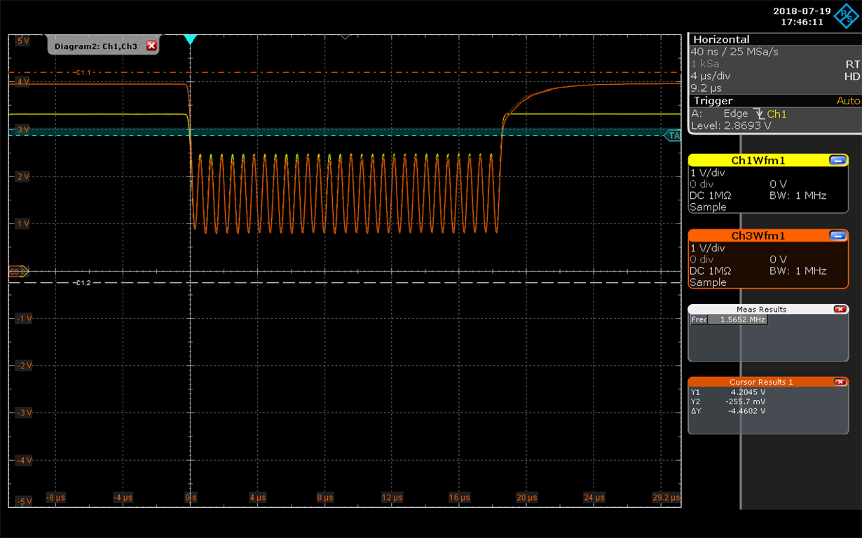
2) As I increased the SPI-speed, MOSI Speed at about 1,5Mhz, the signal of both sites has sinuous shape instead of square -> my question here is how should i define the resistor to have square signal at high-speed

I attachted my schematic and also Oszi capture.

Thank your any advice.

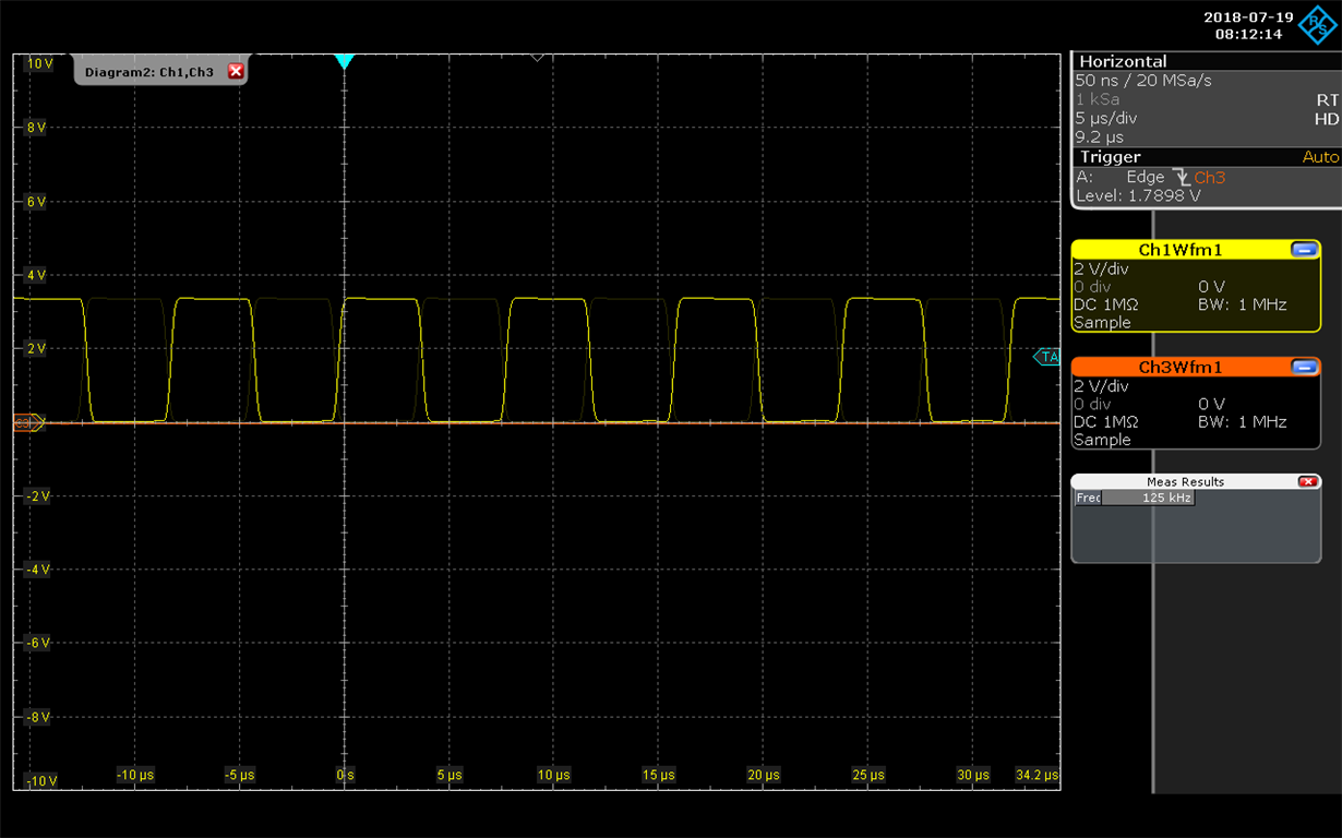
Picture 1 with original SPI-MOSI without connecting with LSF0204D

Picture 2 of same singal MOSI when connecting with LSF0204D at both 3v3 and 5V site

Picture 3: System behavior at high frequency (1.5Mhz MOSI)

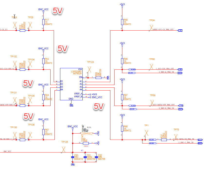
Picture 4: The circuit

Note that ENC_VCC is supplied at 5V. I also tried to change / removed serie resistor (33R2) and it did not changed the result.

  •  I forgot to insert the ciruit

  • Hi Tri,
    It looks like you are using a pretty low pull-up resistor value. I would recommend increasing the 3.3V side pull-up resistors to at least 10k (or remove them entirely), and I would increase the 5V side pull-up resistors to 4.7k.

    The low side voltage increase is being caused by sink current into your driver from all these 1k pull-up resistors. You can see a detailed explanation in this video: training.ti.com/TLM-LSF-Down
  • Hello Mr. Maier,

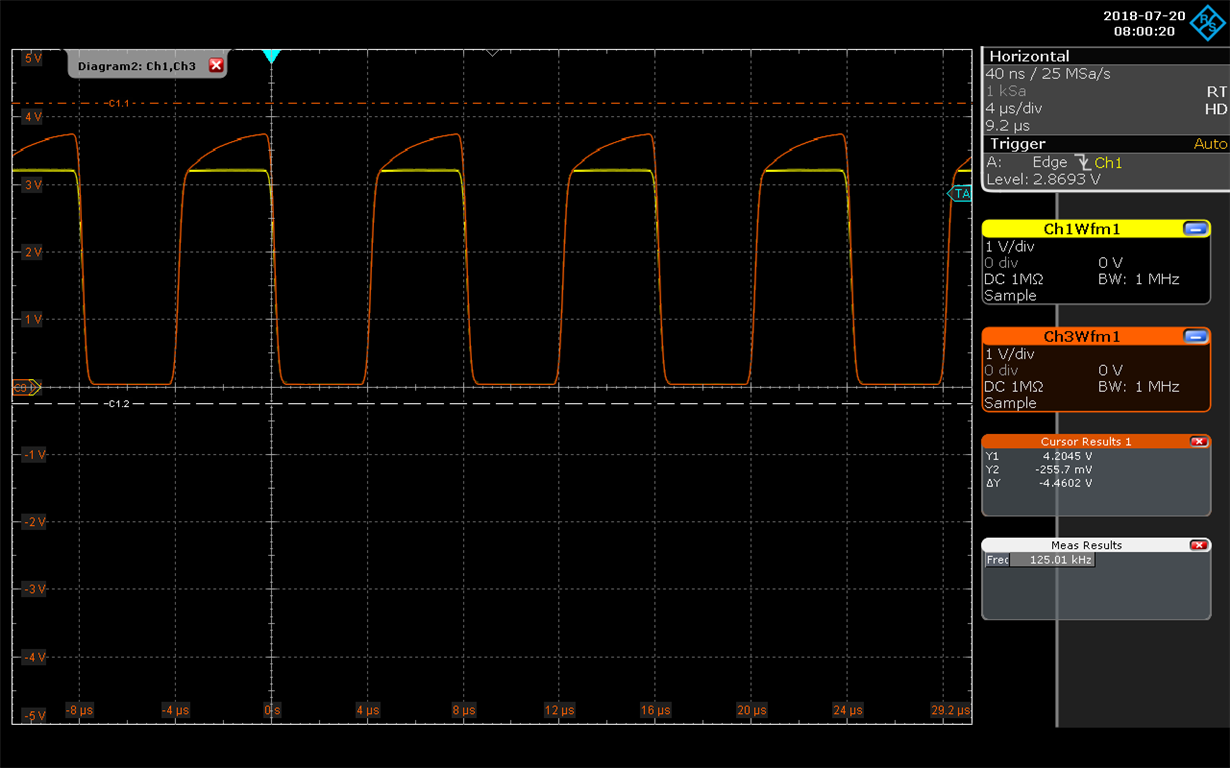
    I tried your suggestion in many ways but it does not have any effect on offset issue. I still have about 1V offset on both 5V and 3v3 sides.

    1) 4.7k on 5V, remove resistor on 3v3 => 0.9V offset both sides

    2) 10k on 5V, remove resistor on 3v3 => 0.9V offset both sides

    3) 10k on 5V, 10k on 3v3 => 0.8V offset on both sides.

    In the picture is yellow signal from 3v3 and red von 5V in configuration with 10k (5V) and blank (3v3). Connecting or disconnecting the high-side 5V component will generate the same result.

    Do you have any other suggesstion?

    Thanks

  • Hi Tri,
    It looks like your signal is much faster here than in the previous post. Do you still see the same offset with a slower signal?
  • Hey Tri,

    Just FYI, there's a slide in the videos I linked that talks specifically about the issue you are having.

    This is in the "up-translation" video at 4:57: Up Translation with the LSF Family

    There are limitations to using a passive translator that are specifically related to loading and drive strength of the surrounding devices. I would highly recommend watching all these videos to understand what's going on and decide if LSF can support your system's translation requirements.

  •  Hello Emrys,

    You're right. The offset on both sides is eliminated at slow speed (of SPI) but the signal on B-Side does not reach 5V level.

    Does it mean that LSF0204D is not able to run at high speed (6Mhz SPI).

    Thanks

  • As described in the video I linked, there is a balancing act when designing with a passive translator. I can see from your scope shot that the RC constant on the output is very slow with a 4.7kohm resistor. Decreasing the resistance will speed up the edges, but it will also require additional current from your driver, which will increase the low level voltage.

    The only other thing you can change is the load capacitance. We recommend placing the LSF device as close as possible to the higher voltage device to reduce parasitic capacitance from the board, traces, and connectors. If this is not an option, then you may need to switch to a semi-active or active translator.