This thread has been locked.

If you have a related question, please click the "Ask a related question" button in the top right corner. The newly created question will be automatically linked to this question.

SN6501-Q1: SN6501

Part Number: SN6501-Q1
Other Parts Discussed in Thread: SN6501, TIDA-01605, TL431, TLV431

Dear TI team,

I created a circuit in PSPICE for TI software, but there are always below error. Could you please help me to rectifier it? I attached the simulation model with this post. And below is its schematic.

"WARNING(ORPSIM-15220): Error in opening Alias File : C:\SIMULATION\sn6501-pushpull-PSpiceFiles\SCHEMATIC1\SCHEMATIC1.als"

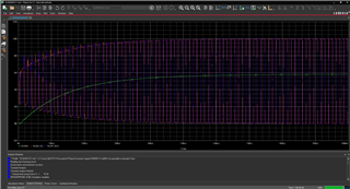
One more thing is that when I run an example model available in the software, the simulation run very slow. Could you have any idea how to increase simulation speed of PSPICE for TI software?

Thank you in advance. Regards,

SN6501-PushPull-PSpiceFiles.zip

  • Hi Van,

    Thank you for posting to E2E! I've opened this simulation project and found the same error you mentioned.

    It seems the "WARNING(ORPSIM-15220): Error in opening Alias File : C:\SIMULATION\sn6501-pushpull-PSpiceFiles\SCHEMATIC1\SCHEMATIC1.als" message is related to the configuration of the SN6501 model -- the two single-winding transformers are not coupled, therefore they do not allow the SN6501 to operate properly.

    At the moment it isn't clear whether replacing this transformer with a push-pull transformer model will allow the simulation to run error-free, but I am checking whether it eliminates the warning mentioned above. At this time, TI does not have a generic transformer model to use with SN6501 (besides the one included in the reference design), so please do ask the manufacturer / vendor of the transformer part you are using for a PSpice model to integrate to your circuit.

    Regarding the slow simulation speed, please allow me 1-2 days to check on this also and confirm if there is a specific reason why this might be occurring.


    Thank you,
    Manuel Chavez

  • Dear Manuel,

    Thank you so much for your reply. In application note TIDA-01605 attached below, there are simulation results for Push-pull converter using SN6501 controller. Do you have this simulation reference file that can send me?

    Alternately, I have created a simulation model in LTspice. I downloaded transient model of SN6501 (attached below) from TI website and imported it into LTspice and made a simulation model (attached below) in Zip file. However, the speed of simulation is very slow (the simulation model looks simple). I don't know whether this is problem associated with transient model of SN6501 or not. Could you please check my LTspice model to see this issue?

    Thank  you so much. Regards,

    TIDA 01605_SN6501PushPull.pdfSN6501PushPull.zip0131.SN6501_TRANS.lib

  • Hi Van,

    You're welcome! In TIDA-01605, simulations shown are of the SiC MOSFET circuitry.

    I apologize, but we cannot support LTspice simulation models or analysis. Attached below is a PSpice simulation project with a simple SN6501 circuit that can be used for your analysis.

    SN6501 circuit.zip

    Ensure you have the latest version of PSpice for TI (2021.1 version 17.4-2020) to run this project and ensure "skip initial bias point (SKIPBP)" in the simulation settings is checked, and you will be able to run 100us of simulation within 2 minutes. The transformer might have a delay that does not allow it to converge earlier, so shorter simulation times might be problematic. Below is a screenshot of a completed simulation using this folder:


    If error messages appear during simulation, most of them can be resolved by selecting the "Autoconverge" option and resuming the simulation. Please let us know if you have any trouble or additional questions.


    Thank you,
    Manuel Chavez

  • Dear Manuel,

    Thank you so much for your feedback. It is greatly helpful!

    I found where I made mistakes. In SPICE simulation, both the secondary and primary should have the same ground in order for the simulation to run properly, even though in reality, they are isolated.

    I just have one more question. In the figure below from application note TIDA 01605, TL431 is used for regulating -4V signal. And the +15V will be the remaining voltage from the total output of secondary. However, regulating +15V may be more important because it will decide the Rdson of the MOSFET. How can I modify the circuit so that I can regulate 15V exactly? (-4V will be what remains from the output voltage). 

    I have tried different connection but it does not work.

    Thank you so much for your help. Regards,

  • Hi Van,

    You're welcome! We're glad to help Slight smile

    Thanks for sharing feedback about making the simulation work. Regarding the TL431, output voltage can be re-configured using different resistor values, or another output-regulation method can be used, like an LDO.

    If you'd like further assistance with the TLV431, please feel free to use the yellow button in the top-right corner of this window to "Ask a related question" and list the device as TLV431. This way, the team behind this product can provide optimal support for you.


    Thanks again!
    Manuel Chavez