This thread has been locked.

If you have a related question, please click the "Ask a related question" button in the top right corner. The newly created question will be automatically linked to this question.

ISO1211: VIL, VIH threshold. AC detection details.

Part Number: ISO1211

Hi,

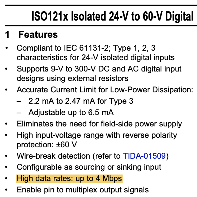
My customer has two questions regarding ISO1211.

Firstly, they want to utilize ISO1211 to do ac voltage detection. They want to know more details about the detection mechanism, when ISO1211 senses the ac voltage, does it sense the instantaneous value at some specific time point, or sense many points during a certain time period, then calculate the effective value? If it is the second case, how long is the time period?

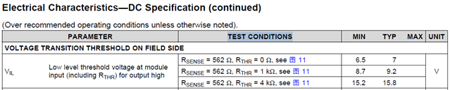
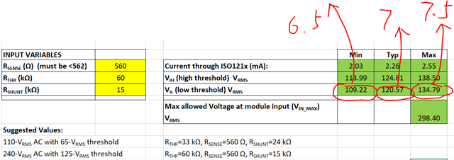
Secondly, in the datasheet, 6.9 Electrical Characteristics—DC Specification, here shows the min value and typical value of Low level threshold voltage VIL, as well as the typical value and max value of high level threshold voltage VIH, but how about the max value of VIL and min value of VIH? I see that in the excel calculator, there are some formulas and data to calculate VIL and VIH, but just in one test condition. Can we guarantee the data in the excel calculator? And can we provide more detailed data besides that in the excel calculator? Thanks.

Regards,

Xiaoying 

  • Hi Xiaoying,

    Thanks for reaching out with the questions from customer.

    Regarding input voltage sensing mechanism, the input voltage sensing circuit in ISO1211 is an analog circuit that monitors the voltage continuously. Hence, as soon as the input voltage hits the threshold, the output will change accordingly in one propagation delay. Thus, there is no averaging done here.

    Regarding the VIL and VIH specs in datasheet, please note that min VIL and max VIH are the worst-case thresholds while max VIL and min VIH would be best-case data thresholds. Since customers typically design their system for worst-case conditions, worst-case thresholds have been provided in the datasheet. Typically values are also provided to quickly help know how a quick lab test data looks like at room temperature.

    I see that in the excel calculator, there are some formulas and data to calculate VIL and VIH, but just in one test condition. Can we guarantee the data in the excel calculator? And can we provide more detailed data besides that in the excel calculator?

    Could you please let me know what test conditions you are referring to?
    The calculations provided in the calculator are the approximations to help customer and the actual values observed depend on the resistors used and their tolerances. We guarantee all the specifications provided in the datasheet.


    Regards,
    Koteshwar Rao

  • Hi Koteshwar, 

    Thanks for your reply. And I have some follow-up questions. 

    1. Regarding input voltage sensing mechanism, if the input voltage sensing circuit in ISO1211 is an analog circuit that monitors the voltage continuously, how about the bandwidth of the circuit? What I want to make sure is that, what is the max frequency of ac input that this circuit can respond to, or in other words, what level of sampling rate can ISO1211 can roughly reach?

    2. What I refer to is, for example, in the datasheet, their is min value and typical value of VIL, in three different conditions.

    In the datasheet, the VIL is calculated by 6.5V, 7V and 7.5V, in which 6.5V and 7V corresponds to the data in the first line of the datasheet under the condition of Rsense=562, Rthr=0. So I am not sure if this calculation can help customers to locate the worst case in all situations.

    Also, I want to know that, you mentioned that the calculations provided in the calculator are the approximations to help customer and the actual values observed depend on the resistors used and their tolerances. So the results include both IC deviation and resistor deviation, is that correct? When we list the test conditions and the test results of VIL and VIH, what is the accuracy of the resistors we use to do the test? I am worried that the resistor tolerance of our customer is worse than our test. Can you help provide further advise on this item? Thanks.

    Regards,

    Xiaoying

  • Hi Xiaoying,

    Thanks for elaborating on your questions. Please see my inputs below.

    1. The bandwidth / max datarate that the device input channel supports is specified in the datasheet as 4 Mbps (see image below). We believe this is more than sufficient to cover most industrial digital inputs from the field.

    2. Please note that the values provided as Electrical Characteristics are the actual test data and are not calculated values. The min or the max values are statistical data which the device is never expected to exceed under specified test conditions. While the equations provided later in the datasheet are only for typical test conditions. The calculations provided in the calculator are expected approximations.

    Like I mentioned earlier, for VIL the minimum value is the worst-case. Under worst-case test conditions, it is important for customer to know what is the lowest voltage where the output turns LOW. Triggering higher than typical is not as critical and is going to be the best-case. When the input voltage is falling, triggering at higher voltage is early while triggering at lower voltage is late. Hence, the worst-case is the latest voltage where output turns LOW.

    Similarly, when the input signal is going high, the latest voltage is max VIH and hence, is the worst-case. Triggering early at lower voltage is always good and that's the best case.

    Regarding the equations, the equations do not consider any resistor tolerances or variations, they only provide approximate calculations. But the test data provided in the datasheet are tested using 1% resistors.

    Could you please let me know what exactly is the concern by customer. The variations in VIL and VIH values are really very small when compared to the overall input voltages. Since the input is a digital signal, customers usually do not care much about a small variation in thresholds as the output will still be reproduced matching its input signal accurately. Let me know, thanks.


    Regards,
    Koteshwar Rao

  • Hi Koteshwar,

    Thanks for your detailed explanation!

    I think most of the doubts have been resolved, and the final remained problem is as you mentioned, what is the concern of customer. That is, they want to know the exact source of error of VIH and VIL shown in the datasheet. The internal IC variation among different batches, the temperature drift, or sometimes the resistor tolerance? As you mentioned, the test data provided in the datasheet are tested using 1% resistors, can we assume that because there are enough test cases, the resistance error has been already included in the result? Or our customer should still consider the accuracy of the resistance additionally when doing calculations? Thanks!

    Regards,

    Xiaoying

  • Hi Xiaoying,

    Thanks for further inputs.
    Yes, customer can assume 1% variation in the resistor values as included in the thresholds specified in Electrical Characteristics table.The data published in datasheet already covers device temperature variation and sample-to-sample variation.

    If customer uses resistors with higher tolerance than 1%, then they would have to consider that into account. Thanks.


    Regards,
    Koteshwar Rao