This thread has been locked.

If you have a related question, please click the "Ask a related question" button in the top right corner. The newly created question will be automatically linked to this question.

ISO3082: ISO3082 Unexpected failure

Part Number: ISO3082
Other Parts Discussed in Thread: ISO1410

Hello,

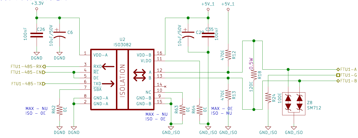
We are using ISO3082 in Industrial environment for communication over fairly long distances of 300-500 meters at 9600bps. Here is the partial schematic,

Please note that we don't use the bias resistors and same board is also used with MAX14945EW+, depending on part availability. R62, R63 are 0E & R64 OPEN when ISO3082 is used.

We have so far used around 1200 ISO3082s over the last 12 months.But we're now seeing random failures of ISO3082, around 2-3 per month over last 3-4 months.

  • There are no visible damages to IC, nor are there any supply short or other pin shorts on any of the damaged units. IC simply stops communicating. After replacing only the damaged IC, everything works fine.
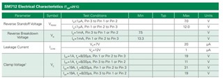
  • TVS SM712 is also not damaged in any of the cases.
  • There are total 6 ISO3082s on single board, all fed from same +5V supply(output side) independent of supply for input side, but only 1 or 2 fail.
  • There are no damages on input side ever.
  • At Other end of comm. links, there are different RS485 bus drivers, like SN75176(@ 5V), MAX3485(@ 3.3V) & Serial-USB Converter Module.
  • Around 50% of the failures are with Serial-USB Converter Module. These are procured by customer & beyond our control.
  • We always use 2-Wires A/B only. And cables are twisted pair with non-flammable PVC cover. Since our systems are replacing older systems, we have to use the per-existing cabling.
  • Cable ducts carrying the communication cable sometimes also carry the 230VAC supply cables to remote stations.

What could be causes of IC failure? What measures can we take to avoid or at least minimize the IC failures?

Thanks in advance,

Saumitra A Deshpande

  • Hi Saumitra,

    Sorry to hear about the issue and thanks for reaching out.
    The schematic looks good and I do not see any issues with it. To help debug the issue, could you please help us with below information.

    1. Do you see the failures occur only with ISO3082 or do you see them with MAX14945 as well?
    2. What percentage of devices are ISO3082 and MAX14945 on the PCB?
    3. From what I understand, ISO3082 stops communicating when there is a failure and it doesn't communicate any further.
      1. Did you test those failed samples in the lab for working? Maybe by applying inputs to them and monitoring the output?
      2. If yes, could you please let me know if the device was working?
    4. Please do also help us with the resistance values of each pin to its local GND for the failed device after it is depopulated from the PCB. If you could also help us the resistances of a good working or untested unit for reference, that would save some time for both of us.

    I am not sure if it is an option for you at this time, ISO1410 is our latest RS-485 device that is pin compatible to ISO3082. ISO1410 has superior overall performance over ISO3082.

    Please do help us with the requested information to debug the issue further, thanks.


    Regards,
    Koteshwar Rao

  • Hi Koteshwar,

    Thanks for the reply.

    • We have designed the PCB for MAX14945 & ISO3082 both, but we have not used the MAX14945 on any units deployed in the field. MAX14945 is only used in our test setup so far.
    • All  6 x RS485 drivers on PCB are ISO3082.
    • We didn't get to test the failed ISO3082s in our lab so far. Only indication of failure is IC not communicating with other end & doing it successfully when replaced
    • Approx Input side resistances with respect to GND1 are, VCC1-GND1 : 860k, R-GND1 : 1.07M, RE-GND1 : 1.22M, DE-GND1 : 950k, D-GND1 : 1.24M. All GND1 are 0E
    • Output side resistances with respect to GND2 are, VCC2-GND2 : 899k, NC(15), B, A , NC(11)-GND2 : Open. All GND2 are 0E
    • Resistances on non-working as well new unused ISO3082 are approximately same.
    • With over 1200 ISO3082s in field, we don't have option to replace those with any other IC.

    Thanks,

    Saumitra A Deshpande

  • Hi Saumitra,

    Thanks for sharing additional information as requested, this helps me understand the situation better.

    From the resistance values that you have shared and from the confirmation that you have provided that both working and non-working devices have the same I/O resistance to their respective grounds, it doesn't quite seem like the device is damaged. As a next step of debug, please do try to test the device and monitor input output waveform. If you do see anything unusual, please do share me the waveform.

    I will also check with my other colleagues on this issue on Monday and see if I can provide any further debug steps. Thanks.


    Regards,
    Koteshwar Rao

  • Hi Saumitra,

    Thank you for sharing the schematic and the debug information!

    I want to point out that the TVS diode by itself isn't sufficient to protect the transceiver.

    Based on the datasheet, the absolute maximum ratings for the bus pins are -9V and 14V.

    The SM712 clamping voltages are 19V at 1A and 31V at 19A.

    Therefore, we should place a 10ohm resistor between the bus pins and the TVS diode

    to cause a voltage drop from the TVS diode to the bus pins. Please refer to this TI design

    and section 9.2.2 of this datasheet for details.

    Could you please perform a curve trace on bus pins of the damaged device and

    a functioning device? We will have a better insight into the damaged device with this information. 

    Regards,

    Alfred

  • Hi Saumitra,

    As pointed out SM712 TVS diode by itself does not fully protect the BUS. 

    If you have a follow-up question, please use the Ask a related question button on the top right to post your question.

    Regards,

    Alfred