Other Parts Discussed in Thread: ISOW7741
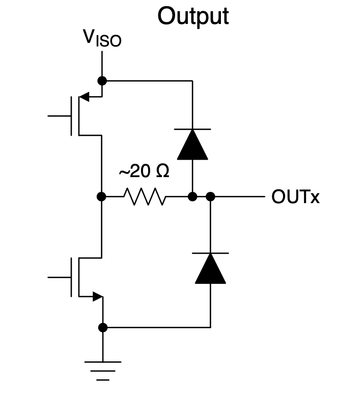
. If we were to connect the non-isolated side of two of those together but power only one at a time, would the “Undetermined state” of the outputs (pins 4-6) of the unpowered device conflict with the output of the powered device? In other words, will the outputs be tri-stated at the unpowered and therefore only driven by the powered or will the unpowered device allow current to flow into/out of its pins when its Vcc (Pin 1) is disconnected?