This thread has been locked.

If you have a related question, please click the "Ask a related question" button in the top right corner. The newly created question will be automatically linked to this question.

ISO7762-Q1: MISO problem when a master device communicates with several slave devices on independent isolation planes.

Part Number: ISO7762-Q1
Other Parts Discussed in Thread: ISO7741

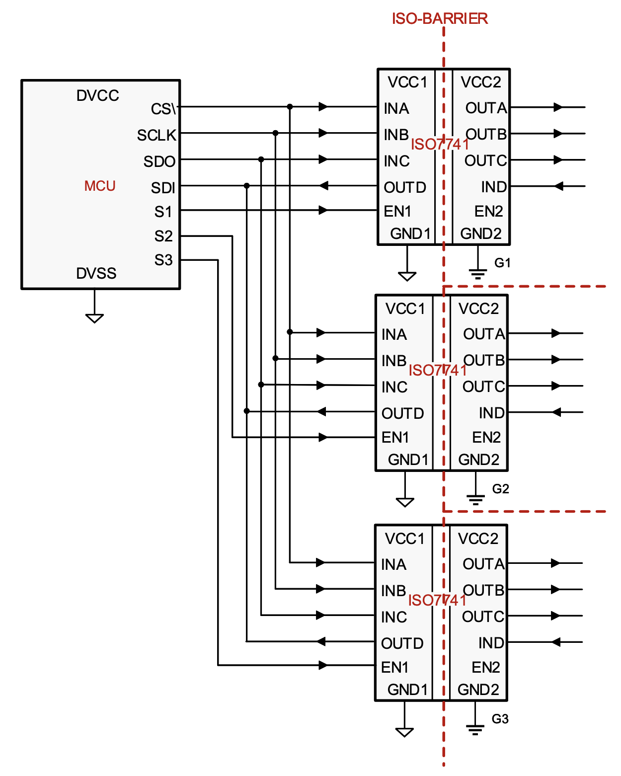
I have a u-Controller which communicates with several slaves using SPI-bus. The slaves are all isolated from u-Controller and each other, each of them in its own isolation plane.
The problem is that the return data-line need to be common (going to MISO). Connecting the isolators outputs together causes very strange voltage level of the signal and some non-recognizable data on it.
I was trying to separate the outputs using a Schottky diode on each of them, connecting the cathodes together and providing it this way to the MISO. Still not working - the cathode is always high level even I am trying to pull it down by resistor. Strangely the signals on the anodes are all exactly as they should be - do not understand why the cathode is permanently high logical level.
Any help would be highly appreciated!

  • Hi Pavel,

    Welcome to TI E2E forum and thanks for showing interest in TI digital isolators.

    I believe I understand challenge you are facing here, the best way to control the receive channels of multiple SPI nodes is to control them through enable pins and enable them individually. Please go through the below FAQ on this topic and do try to implement the suggested approach. This does mean that you will have to switching to a 4-channel device instead of a 6-channel as 6-channel devices do not have enable feature. 

    Let me know if you have any questions, thanks.

    https://e2e.ti.com/support/isolation-group/isolation/f/isolation-forum/991655/faq-how-to-connect-spi-mcu-to-multiple-isolated-spi-nodes


    Regards,
    Koteshwar Rao

  • Hi,

    Thank you for the answer, I've seen it already, while I was searching for solution...
    Unfortunately the things are much more complex as I explained only a simplified version of an already build complex prototype board with several thousand components on it. I am trying to find a working solution even the modification may be very difficult.
    I do use separate ChipSelect (CS) inputs from the u-Controller, so only one slave is communicating at a time, but I have no possibility to disable the isolators itself for these particular prototypes.
    Maybe I need to find some buffers with integrated enable signals to try to separate the isolator's outputs?

  • Hi Pavel,

    Thanks for sharing additional insight into your application. 

    I understand your constraint that there is no possibility to disable the isolator output in your existing prototype. Yes, using buffers that can tri-state the outputs through an enable pin can allow connecting of multiple output pins from the isolator. Alternatively, like I have mentioned in my previous post, you could as well consider using ISO7741 with enable option instead of the 6-channel device that doesn't have enable feature. This allows you similar capability as using buffers without increasing device count.

    I hope this helps you with what you were looking for. Let me know if you still have any further questions, thanks.

    Regards,
    Koteshwar Rao