This thread has been locked.

If you have a related question, please click the "Ask a related question" button in the top right corner. The newly created question will be automatically linked to this question.

ISOUSB211: ISOUSB211 does not working on customer's PCB

Part Number: ISOUSB211

Hello TI experts,

last time I asked about design questions of ISOUSB211 ;

https://e2e.ti.com/support/isolation-group/isolation/f/isolation-forum/1071321/isousb211-how-to-set-eqxx-pins/3969849#3969849

then they made their own PCB and tested it, but it does not work at all.

I attach a latest schematic and layout. could you check it and advise me how to test?

(USB B(CN1) is connected to PC, and USB C(J1) is connected to camera module C8282P.)

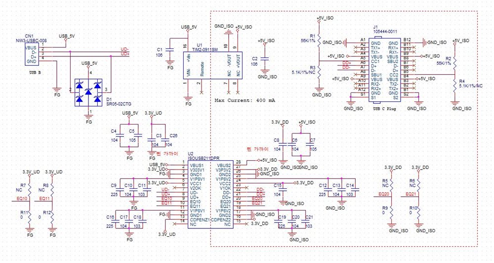
they connected pin4 and pin11 / pin18 and pin25 manually.

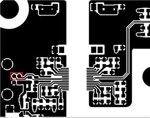
and here are layouts. they use 2 layer PCB.

ISOUSB211_TOP.pdf

ISOUSB211_TOP SILK.pdf

ISOUSB211_BOTTOM.pdf

ISOUSB211_BOT_SILK.pdf

and here is the spec sheet of camera module (for your convenience.)

1.3 MUC 108 backend C8282P.PDF

Please check this issue, and let me know if you want more information about it. Thanks.

Best regards,

Chase

  • Hi Chase,

    Thank for reaching out to us!

    1. Do the Vcc1 and Vcc2 powered by 3.3V sources from the system? You can't tie the Vcc1 to V3P3V1 and Vcc2 to V3P3V2 since the internal LDOs do not have enough current to drive the VCC1 and VCC2. In our previous e2e, we mentioned that these VCC pins should be connected to external 3.3V source.

    2. Could you please clarify "they connected pin4 and pin11 / pin18 and pin25 manually"? Why are the ground pins connected manually?

    3. How are the UD+ and UD- routed to the USB connector? They stop at the red highlighted square.


    4. Could you please plug the muC108 camera directly to the PC to confirm that it is compatible with the PC.


    Regards,

    Alfred

  • Dear Alfred,

    Thank you for your support again.

    1. I searched datasheet again, it has something unclear.

    - we use USB 5V for the system. so we can connect only bypass capacitor to V_3P3V1(P2), In this case internal LDO generates 3.3V.

    - in the description of P5(Vcc1), if 5V supply is available, connect 5V to Vcc1. in this case internal LDO generates 1.8V.

    - so what is the exact description? does internal LDO make 3.3V or 1.8V? otherwise does ISOUSB211 have 2 internal LDO?

    - and please confirm if I use USB 5V only for the system;

    :: connect USB 5V to Vbus1 (P1)

    :: connect only bypass capacitor to V3p3v1 (P2)

    :: connect only bypass capacitor to V1p8v1 (P4)

    :: connect USB 5V to Vcc1 (P5)

    :: and draw same on the opposite side.

    2. in the description of P11, it says that connect pin11 to pin4, with local bypass capacitors near pin 11. and same as P18.

    3. the red square is the end of the routing. it is USB connector including power and GND.

    4. yes, the camera is working if I connect it directly to PC.

    please check this issue, and let me know if you want more information. Thanks.

    Best regards,

    Chase

  • Hi Chase,

    Thank you for providing the additional information!

    The datasheet provides multiple configurations to meet customers needs.

    The are 4 LDOs in ISOUSB211. Two LDOs generate V3P3V1 and V3P3V2, and the other two LDOs generate V1P8V1 and V1P8V2.

    Below are the common use cases.

    Case 1: When only 5V external power is available, VBUSx and VCCx should be connected to this 5V external supply. The 4 internal LDOs will generate 3.3V and 1.8V respectively.

    Case 2a: When 5V external power supply and 3.3V external power supply are available, VBUSx connect to 5V external power supply and VCCx connect to 3.3V external power supply. This will lower the system power consumption. The 4 internal LDO will generate 3.3V and 1.8V respectively.

    Case 2b: When only 3.3V external power supply are available, VBUSx and V3P3PVx connect to external 3.3V power supply. Hence, 2 of the internal LDO will not be used to generate 3.3V.  VCCx should be connected to the external 3.3V power supply. The other 2 internal LDOs will generate 1.8V.

    Case 3: When 3.3V external power supply and 1.8V external power supply are available, VBUS and V3P3Vx connect to the external 3.3V power supply. VCCx and V1V8V2 connect to the external 1.8V power supply.

    The V3P3Vx generated by internal LDOs should not be used to drive the VCCx because they can't support the current requirement for VCCx and the other 2 internal LDOs to generate the 1.8V for the high-speed circuitry.

    2. The pin 4 and pin 11, and pin 18 and 25 is recommended to be connected through layout for good practice.

    For a quick workaround, I suggest cutting the VCCx from the V3P3Vx. Then connect the VCCx to the 5V external power source.

    Regards,

    Alfred

  • Hi Chase,

    I hope you have resolved the issue. I will close this e2e post. 

    Please use the top right "Ask a related question" if you have a related question.

    Regards,

    Alfred