This thread has been locked.

If you have a related question, please click the "Ask a related question" button in the top right corner. The newly created question will be automatically linked to this question.

ISO3080: R output state is Lo constant

Part Number: ISO3080

Dear, support team.

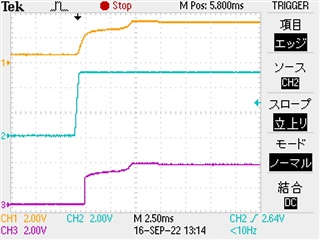
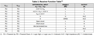
The R output may be stuck LO after powering up the ISO3080.
For example, are there any restrictions on power sequencing or power ramp ramps?
Even removing L19 from the schematic in the EXCEL file didn't change anything.ISO3080.xlsx
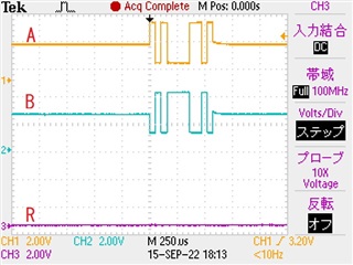
Best Regards,
Hiroaki Yuyama

  • Yuyama-san,

    Thank you for providing oscilloscope screenshots and a schematic. 

    There are no power sequencing restrictions for this device. VCC1 and VCC2 can be powered in any order.

    Can you please confirm that the oscilloscope probe is working correctly? And could you also confirm that the oscilloscope settings are all configured correctly for this measurement?

    I also see in the schematic that you have two 1 KΩ resistors connected to the A and B pins of this device (R249 and R250). Can you short these resistors and take the same measurements again?

    Regards, 

    Kenneth

  • Hi, Kenneth-san,
    Thank you for your support.

    RS-485 receiver BUS A and B are differentially oscillated around a common mode voltage of about 2V.
    We shorted(=0ohm) the 1kohm series resistors of the RS-485 receiver BUS A and B and took the waveform.
    Yellow = A input
    Green = B input
    Purple = R output

    If the R output is constant LO, the R output will be constant LO from power-up of the power supply.
    Yellow = VCC1 3.3V
    Green = VCC2 5.0V
    Purple = R output

    For good devices, Rout goes Hi after power-up.
    Both RS-485 receiver BUS A and B inputs are open circuit at this time.
    Yellow = VCC1 3.3V
    Green = VCC2 5.0V
    Purple = R output


    In the datasheet Table 3, when A and B are open circuit, the R output is H.

    Best Regards,
    Hiroaki Yuyama

  • Yuyama-san,

    Thank you for providing additional oscilloscope screenshots.

    For the second oscilloscope screenshot in the post, are the 1 KΩ resistors on the RS-485 bus still shorted?

    Additionally, in the second oscilloscope screenshot, are the A and B inputs to the device configured as an open circuit? Or are they configured differently?

    Regards,

    Kenneth

  • Hi, Kenneth-san,
    Thank you for your support.

    Yes, the second oscilloscope screenshot leaves the A and B series resistors shorted.
    Even if the A and B input signals are floating or a 100kbps signal is input,
    if R out is Lo after the power is turned on, it will remain Lo all the time.

    Best Regards,
    Hiroaki Yuyama

  • Yuyama-san,

    RS-485 receiver BUS A and B are differentially oscillated around a common mode voltage of about 2V.
    We shorted(=0ohm) the 1kohm series resistors of the RS-485 receiver BUS A and B and took the waveform.
    Yellow = A input
    Green = B input
    Purple = R output

    In the oscilloscope screenshot above, was this behavior observed on a device that wasn't working before you shorted the 1 KΩ resistors, or was it observed on a device that was already working before any changes were made?

    Also, for a bad device, does the receiver output pin (R) ever go high again, or does it always remain low?

    Additionally, I would like to check and see if this unexpected behavior is common across multiple ISO3080 devices. How many different ISO3080 devices have you tested? Of all of the devices that you have tested, how many have behaved in this way?

    Regards,

    Kenneth

  • Yuyama-san,

    Do you have any updates? Were you able to resolve this issue, or are you still seeing results that are unexpected?

    Regards,

    Kenneth

  • Hi, Kenneth-san,
    Thank you for your support.

    We are still investigating the cause.
    In our customer's production line, there is one that does not follow the signal from the time the power is turned on and R Out is fixed at Lo for 8 units/1500 units.
    R out that failed to start power supply does not follow at all even if a signal is applied.
    If you turn off the power again and power up, there are rare cases where R Out follows.
    We are still investigating the cause while checking the power sequence and ramp-up speed.

    Best Regards,
    Hiroaki Yuyama

  • Yuyama-san,

    Thanks for the update.

    The behavior that you have observed is not expected. Please reach out to your TI representative so that the units behaving unexpectedly can be submitted for failure analysis. We will take a look at these samples once we receive them. 

    I will go ahead and mark this post as closed. We will continue to work on this issue offline once we receive samples.

    Regards,

    Kenneth 

  • Hi, Kenneth-san,
    Thank you for your following.

    Our distributor sent samples and analysis to TI.

    Best Regards,
    Hiroaki Yuyama