This thread has been locked.

If you have a related question, please click the "Ask a related question" button in the top right corner. The newly created question will be automatically linked to this question.

SN6507DGQEVM: XSN6507DGQR

Part Number: SN6507DGQEVM
Other Parts Discussed in Thread: SN6507

Hello,

I am using the SN6507 EVB of the push pull converter.

Circuit parameters:

1. frequency is 150kHz (Rclk=82kohm)

2. ILIM resistor is 18k (1.3A)

3. Input voltage is 12V

4. Output voltage range: 50-60V, 0.4W max

5. Custom Transformer parameters: Turn ratio N=7, primary inductance and resistance (from SW1 to VCC and from SW2 to VCC) is 80uH and 5ohm, primary leakage inductance is 60nH.

6. I am using inductor at the output to get the output voltage as a function of the duty cycle

To get 50V at the output i need to set the duty cycle to 30%: Vout=Vin*N*2*D

but i started at first with 48% duty cycle

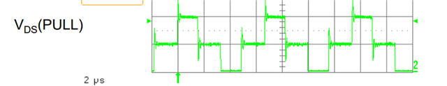
I measured the drain voltage with a probe and this is what i get: 48% duty cycle and 82V at the output - making sense so far

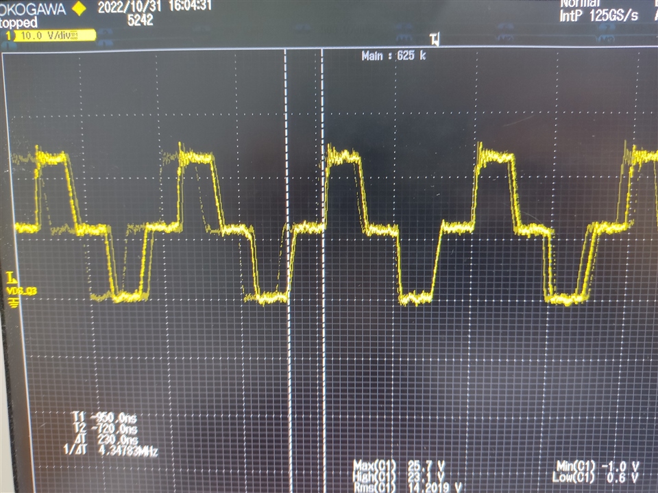
Than I decreased the duty cycle to 30%

so, from the formula in the datasheet i need to select RDC as 242kohm.

This is what i get: still 48% duty cycle and 82V at the output

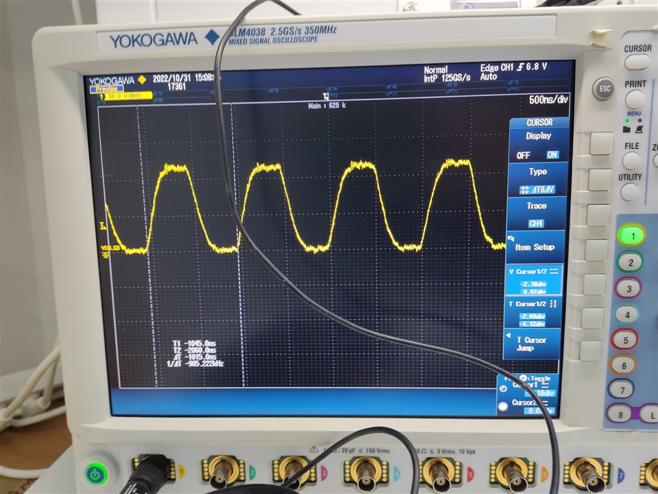
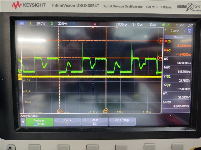
Than i decreased the duty cycle to 20% to see the impact of the drain voltage

so, from the formula in the datasheet i need to select RDC as 160kohm.

This is what I get: still 48% duty cycle, 82V at the output and the drain wave changed a bit

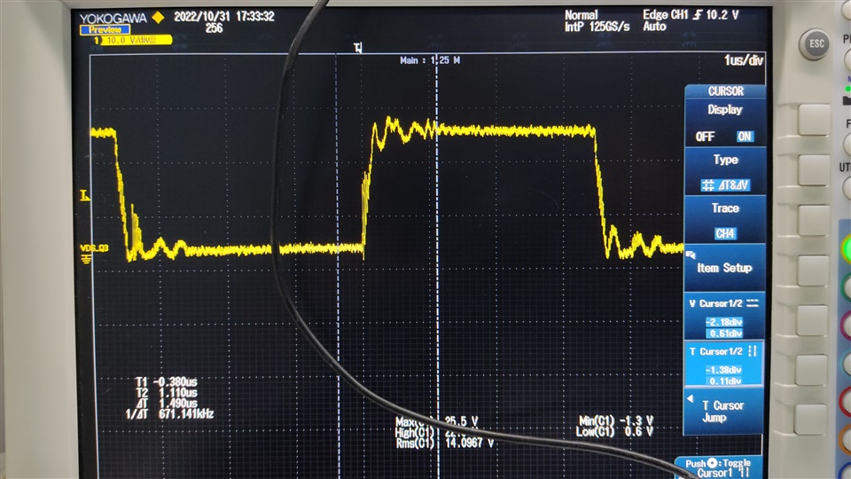
Than I replaced the transformer with the transformer of the EVB (750319696)

The Turn ration is 1/1.29, primary inductance: 150uH, primary resistance: 10ohm

This this what I get: 24V at the output instead of 3.7V (from the formula Vout=Vin*N*2*D) and duty cycle unknown

Than I removed the transformer and soldered 60ohm resistor between SW1 to VCC and this is what I get: 20% duty cycle, making sense

Do you know what could be the problem?

Thank you

  • Hi Maor,

    Thanks for reaching out and for sharing all the details related to the issue you are facing. Please see my inputs below,

    1. Frequency and ILIM resistor selection looks good.
      • 5. Custom Transformer parameters: Turn ratio N=7, primary inductance and resistance (from SW1 to VCC and from SW2 to VCC) is 80uH and 5ohm, primary leakage inductance is 60nH.

      Transformer turns-ratio doesn't seem correct. The turns-ratio, N, should be calculated using equation 18 from the datasheet, also copied below.

      1. Using the above equation and VF-max = 0.5V, VDO-max = 0V, VO-max = 60V, VIN-min = 12V, RDS-max = 1Ω, and ID-max = ~50mA, the turns-ratio is calculated to be as N = 5.2.
      2. If you use a transformer with a turns-ratio of 5.2, you should get an output voltage that is close to 60V.
      3. Duty Cycle (DC) control is not be used for setting the output voltage, this is only needed for line regulation. i.e., if you expect a variation at the input voltage (12V in this case) then DC control can minimize the impact of input voltage variation and maintain output regulation. But the actual output voltage is set by the transformer turns-ratio. Using N = 7 is not suitable for your application.

      As stated above, DC control should only be used for improving line regulation when the input voltage is expected to have variation and should not used for setting output voltage.

      May I know what is the V-t product of the transformer? One of the first design requirements for the transformer is to make sure it meets the V-t product requirements of the design (refer equation 9). From calculations, V-t(min) is estimated to be as 40Vµs. Please confirm if the transformer chosen meets this requirement.
      • This this what I get: 24V at the output instead of 3.7V (from the formula Vout=Vin*N*2*D) and duty cycle unknown
      What is the input voltage, RDC, RCLK? If RCLK is still set to 150kHz then the EVM transformer might not work as that was designed for V-t products that is suitable for 1MHz. If you restore all the values to default EVM configuration then it should work fine.
      When resistors are used instead of transformer, then you will see the switch action from device to be fine. It is the transformer that doesn't work when its designed for some parameters but is being used for other test conditions. i.e., transformer was designed for 1MHz but is being tested at 150kHz.

    I hope above points clarify why your design is not working and what needs to be done to make it work. Let me know if you have any questions, thanks.


    Regards,
    Koteshwar Rao

  • Hi Rao,

    Thank you for your detailed answer!

    1. So my transformer maybe enters saturation? This is why i see the ugly waves and the duty stuck at 48% when i change it?

    2. This transformer is custom (made by me), how do i calculate the maximum allowable v-t product?

    3. Why the duty cycle is not determines the output voltage? If i set it constant with a resistor in the DC pin and the transformer is not saturated, than if i will solder another resistor the output voltage will change?

    4. Did you meant that the transformer should be with N=5.2 and with 48% duty cycle to get 60V?

    5. Can i stay with the N=7 and just increase the frequency to solve the problem (so the transformer will not be saturated)? And work with 30% duty cycle to set the voltage to 50V

    Thank you

  • Hi Maor,

    Thanks for your inputs, please see my response below.

    1. Yes, that seems to be the case.
    2. The V-t product can estimated using transformer parameters. V*t = L*Is = N*A*B
      1. Where L = primary inductance, Is = saturation current of transformer, N = number of turns on primary, A = area of coil/core, B = saturation flux density of the core.
    3. Duty cycle will have an impact on the output voltage observed but what I am trying to say is that duty cycle control is provided to compensate for input voltage variation and it is best used that way. By reducing duty cycle, you would be unnecessarily required to increase turns-ratio which might increase the size of transformer. I understand you already have a transformer with higher turns-ratio and trying to use it.
    4. Yes, your understanding is correct.
    5. Yes, that is possible but you need to know the V-t product to know how much should the frequency be increased. Please do calculate the V-t product of transformer and then you know what frequency is okay using equation V-t = VIN / (2 * Fsw), i.e., Fsw = VIN / (2 * V-t).

    Let me know if you have any further questions, thanks.


    Regards,
    Koteshwar Rao

  • Hi Rau,

    Thank you for your answers

    1. Can you please tell me how you calculate the v-t of my transformer? 

    The transformer parameters:

    N87

    E 16/8/5 

    Praimery turns (from VCC to SW1) = 6

    Secondery turns = 42

    What i put in the B in the equition?

    2. Why is this formula is with '2' and not with the duty cycle instead? V-t = VIN / (2 * Fsw)

    You assumed that the duty cycle is 0.5?

    I cannot change the bobbin since i have already the PCB, only the windings and frequency

    Thank you!

  • Hi Maor,

    Thanks for sharing additional inputs.

    1. V-t = N * A * B
      1. I see you mentioned N = 6
      2. A should be listed in the magnetic core datasheet. I see that E16/8/5 transformer has a cross section area of core of 20.1mm2, you can use this for A.
      3. B is also given in the magnetic core datasheet. For N87 core, this seems to be between 0.4T to 0.5T. You can used these values.
      4. Substituting these values into V-t equation, it is coming to be 48Vµs.
      5. Using VIN(max) as 12V and fmin as 150kHz in equation (9), V-t(min) is calculated to be 40Vµs. When you try to operate at lower duty cycle, the required V-t will go up and 48Vµs V-t product of transformer might not be sufficient. Hence, this is leading to transformer saturation.
      6. Please do refer to your ferrite core datasheet to confirm the actual values and calculate V-t product of your transformer.
    2. Your understanding is mostly correct. Each winding is applied with voltage for half the time period,
      1. i.e., V-t(min) = VIN(max) * Tmax/2 = VIN(max) / (2 * fmin).
      2. Please refer to equation (9) in the datasheet for more details.


    Regards,
    Koteshwar Rao

  • Hi Rao,

    Thank you for your answers, i have some few more questions please:

    1. Why when i decrease the duty cycle the v-t product increases? I dont see that the equition depends on the duty cycle

    2. Can you calculate what will be the v-t product of my design in 30% duty cycle?

    3. What is the suggested hand of thumb rule of the v-t to work with in relation to the v-t of the transformer? 50%?

    4. Do i need to set the current limit to 0.5A? Because in the datasheet it says in the operating recommended conditions maximum 0.5A switch current

    5. i increased the frequency to 300kHz and set the duty to 40% but the drain voltage was a square wave from 0V to 24V with 43% duty cycle (i dont see 12V at the dead time). Why i don't see wave something like this (picture from the internet)?

    Why i see square wave from 0V to 24V without 12V at the dead time?

    6. I added 2 more windings in the primary (8T, 64Vus) and set the duty to 30% with 250kHz, but the duty still was 43% and still 0V to 24V without 12V at the dead time, why is that?

    Thank you

  • Hi Maor,

    Please find my inputs below.

    1. Sorry, when duty cycle is decreased the V-t product requirement goes down as the duration for which voltage is applied also come down.
      1. Duty cycle is not directly included in the equation because the device is not meant to be operated with designed for different duty cycles.
      2. We recommend that the device is used with default duty cycle of 48% for which V-t(min) = VIN(max) / (2 * fmin) as stated in equation 9 of datasheet.
      3. If line regulation is desired, then duty cycle is set to 25% for which V-t(min) = VIN(typ) / (4 * fmin) as stated in equation 10 of datasheet.
      4. Duty cycle is not directly included in the equation but the factor in the denominator represents duty cycle.
    2. V-t(min) for 30% at VIN = 12V and fmin = 150kHz would be, V-t(min) = VIN(typ) / (3.33 * fmin). Hence, the value of V-t(min) should be 24Vµs.
    3. The requirement is to choose a transformer that is rated for a V-t product which is greater than the minimum V-t product required by the application.
    4. Not required. Current limit is only a protection feature and it should be chosen such that the device limits input current when the output exceeds device ratings or gets short circuited. Higher current limit should work for all application and it can be brought down only when the output current requirement is low and you want to limit the current. It is fine to start working with 1.3A in the beginning and adjust this to a lower value later if desired.
    5. Could you please share waveform you are observing during test? So that I can review and confirm what is wrong and how to fix it.
      1. The waveform should switch between 0V and 24V with 43% duty cycle if the input voltage applied is 12V.
      2. The waveform that you showed probably shows both SW1 and SW2 combined for representation purposes.
    6. Please share the waveform so that I can comment. 0V to 24V is the correct waveform for your application.


    Regards,
    Koteshwar Rao

  • Hi Rao,

    Thank you for your answers

    Regarding the waveforms you asked, first here is the waveform of the drain to ground with the original transformer of the EVB with freq of 1MHz and duty of 20% and with load of 150ohm (Vout was 4V like the formula):

    This seems good like in the books, but if i remove the load i get this:

    I think that the Coss capacitor of the mosfet is charging slowly without load at the output.

    Then, i placed my transformer with 150kHz and 30% duty cycle and with load of 1.7kohm (Vout was 80V when from the formula it should be 50V in 30% duty cycle):

    This not seems like the first picture..

    Thank you

  • Hi Maor,

    Thanks for sharing the waveform, this helps.

    The first waveform is good and I believe that looks accurate for switching waveform with much lower duty cycle than 48%.

    The second waveform should also have looked like the first one ideally but since there is no load, the energy stored in the transformer is not being discharged and hence, it slows down the change in voltage. This is probably causing the voltage across MOSFET to appear changing linearly.

    The third waveform looks accurate for a switching waveform with 48% duty cycle. This is also the reason why you are seeing 80V which matches with an expected voltage of 84V for a transformer with a turns-ratio of 7 and input voltage of 12V. I would appreciate if you can share all the information related to this particular waveform or test setup so that I can confirm why the duty cycle is not changing to 30%. Information that I am looking for is,

    1. Input voltage
    2. Transformer turns-ratio (N)
    3. V-t product. I expected a value of 48Vµs earlier assuming A (cross section area of core) and B (flux density). I would appreciate you can refer to the core manufacturer datasheet and provide accurate values so that V-t product can be estimated accurately.
    4. RCLK
    5. RDC
    6. RILIM
    7. RSR

    I would also like to mention that when using duty cycle control, it is must to have an inductor at the output of rectifier diodes as stated in the datasheet. The minimum value of the inductor (LMIN) can be calculated using equation (2) provided in the datasheet. Please note that if you design LMIN for a load of ILOADMIN (like 100mA) then you should only use the solution for >ILOADMIN (>100mA). For currents <ILOADMIN, the output can have lots of ripple. If the intention is to use the solution at 10mA then you should design LMIN for 10mA.

    I would also like to mention that 150kHz is possibly requiring a Vxt product that is too close to the transformer Vxt. So maybe what you can try testing is to increase switching frequency to 500kHz and then test for 30% duty that way the V-t product required is lower. Let me know what you find out, thanks.


    Regards,
    Koteshwar Rao