This thread has been locked.

If you have a related question, please click the "Ask a related question" button in the top right corner. The newly created question will be automatically linked to this question.

ISO1042: Use ISO1042DWVR communication chip, tr and tf delay problem

Part Number: ISO1042

Hi,Expert

The tr/tf parameters in the ISO1042DWVR communication chip specification are as follows:

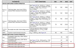
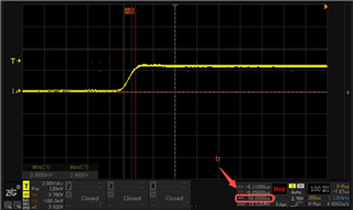
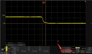
In the actual test, it is found that tf is 54ns and tf is 104ns, both of which exceed the typical values in the specification. Will it affect the communication quality?

In addition, there are only typical values in the specification, so what is the appropriate upper and lower limits without affecting the communication quality?

  • Hi ,

    The driver switching characteristics for the rise time tr and fall time tf are mentioned with Test conditions of RL = 60 Ω and CL = 100 pF. The test setup needs to be similar as Figure 17 in the datasheet. with very small trace to the I/O. The TXD test conditions needs to be met which is mentioned as note A on Figure 17. 

    Also, please make sure that you are measuring the differential voltage between CANH and CANL lines for accurate results. The higher rise time and fall time shouldn't be a problem as the sampling on CAN bus happens in second half of the pulse.

    Thanks
    Vikas J