Other Parts Discussed in Thread: PMP4190, , , SN6505B, TINA-TI
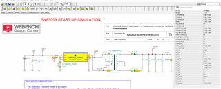
I have design Low wattage SMPS using of SN6505A and PMP4190.
Input-5V(3 to 6)
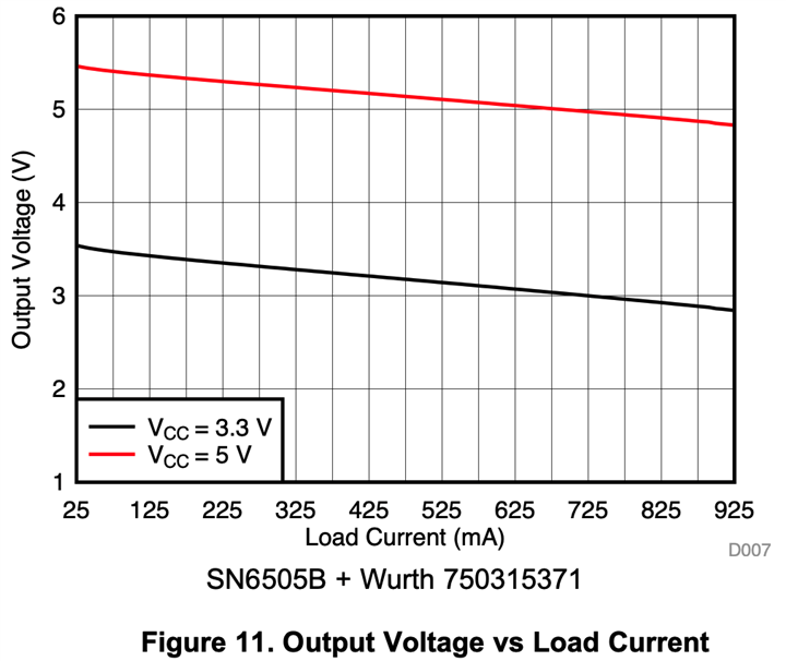
Output- 5V/400mA
Isolation-1500VDC
Please share me reference Design as above part number.
My Mail-vpsingh1020@gmail.com