This thread has been locked.

If you have a related question, please click the "Ask a related question" button in the top right corner. The newly created question will be automatically linked to this question.

ISO7740-Q1: 4 Reverse channel Requirements

Part Number: ISO7740-Q1

Hi Team,

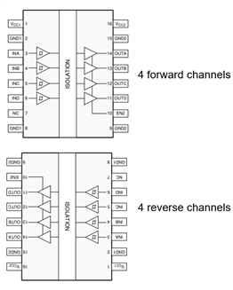
I am using ISO7740FQDWQ1 in my design. My requirement is to have Two 4 channel isolators of one with 4 forward channels and other with 4 reverse channels. But ISO774x-Q1 family doesn't not have 4 reverse channels configuration part. Is there any alternate part with 4 reverse channels configuration with similar features of  ISO774x-Q1 (AEC-Q qualified) ? 

--

Regards,

Kiran

  • Hi Kiran,

    Thank you for your question.

    The ISO774x-Q1 device will still work for your application. Utilizing two ISO774x-Q1 devices will allow you to have 4 forward channels and 4 reverse channels. You can use one device for the 4 forward channels. By turning the second device by 180 degrees in the layout, you can use the second device for the 4 "reverse" channels. 

    Regards,
    Aaditya Vittal

  • Hi Aaditya, 

    1. I am aware of this configuration, but is it the correct way of using the Isolator?

    2. I am using Isolators for M-LVDS transceiver isolation from the Microcontroller. One Isolator will be used for transmitter path and other for the receiver path. If I use one in the rotated configuration, then there will be two different VCC will be facing on the MCU side that is VCC1 for the transmitter isolator and VCC2 for the Receiver isolator. As per the datasheet, VCC2 has a higher power consumption compared to VCC1. Why so? 

    3. Is there any difference in using the Isolator as you shown other than the power consumption difference? 

    --

    Thank you,

    Kiran 

  • Hi Kiran,

    Thank you for your response.

    Below are your answers to your questions:

    1. Yes, using 2 isolators in this manner will work for your application. 
    2. The VCC1 and VCC2 of digital isolators are independent of each other. You will be able to set the VCC pins to any voltage within the recommended operating range specified in the datasheet, which is 2.25V to 5.5V. In terms of the power consumption, VCC2 (which refers to output pins) use more power because it is the output side of the isolator.
      1. for the orientation I provided previously, VCC1 of transmitter and VCC2 of receiver (or VCC1 of isolator 1 and VCC2 of isolator 2) are going to be the same side and same power net. This is not a concern as long as isolation barrier is maintained.
    3. There are no differences besides power consumption for the VCC2 side of the isolators.

    Regards,
    Aaditya Vittal