Tool/software:
I am using this component for RS422 commuinication but for some reason it failed in conducted and radiated emission 
what should I do ? What do you suggest?
This thread has been locked.
If you have a related question, please click the "Ask a related question" button in the top right corner. The newly created question will be automatically linked to this question.
Tool/software:
I am using this component for RS422 commuinication but for some reason it failed in conducted and radiated emission 
what should I do ? What do you suggest?
Hello Sherbel,
Thank you for reaching out. Unfortunately, there is not a lot that I can gather from just the schematic. In general, I would recommend removing the common mode choke and then testing again. Also, please make sure that the cables used for the test are as short as possible since emissions tests can be extremely test-setup and layout dependent.
What emissions standard is being tested and what frequencies are failing? Can you share the emissions plot?
Best,
Andrew
Hello Andrew
![]()

I will give you more details and information, maybe you can help us.
In 2021 we tested our device with RS485 communication , and there was no common mode choke (L1) no 10 PF (C10) between lines Z and Y and the device was connected to display directly (we can say by cable) to component of communication in the scheme below: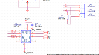
We failed with the conducted emission (We didn't the radiated emission because we did not pass the conducted emission):
When we added common mode choke (L1) and 10 PF (C10) between lines Z and Y... Then we passed the conducted emission: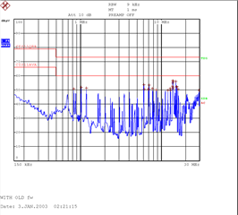
This year we have done changes to display and this once we wanted to test RS422 communication .
So the display communication was like that:
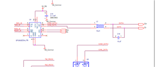
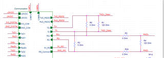
Actually we can say we added common mode choke and capacitor to transmitter of display....
So when we did the test with RS422 we failed Conducted emission and radiated emission:
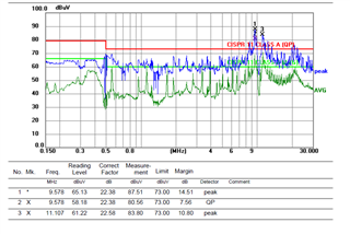
After that we added ferrites to the cables from both sides then we passed in Radiated Emission and we failed in Conducted Emission: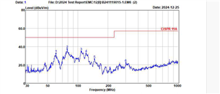
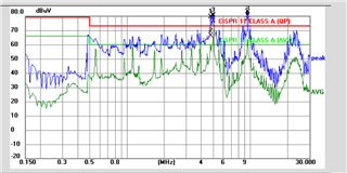
So because in RS422 there is transmitter and receiver (Full duplex) then probably the problem in the lines of receiver of device and transmitter of display (with the common choke and the capacitor) although there is no messages in the transmitter of display but it still may be the problem....
Sorry of this long history... What you think about it?
We think, that we should remove the common mode choke and the capacitor from the display and if we want to added we should add it for the receiver of the device (we cannot remove it from the transmitter of the device because it helped us to pass the tests when it was RS485)... What do you think?
Hello Sherbel,
Thank you The detailed description, it will take me some time to review everything. I will get back to you tomorrow.
-Andrew
Hello Sherbel,
Thank you for waiting. Some additional points that need clarification.
I am seeing the display schematic that has a non-isolated transceiver (SP3070), and I understand that you added a CMC, capacitor and ferrite beads which allowed your system to pass radiated emissions, but conducted emissions is still failing in your new design.
Best,
Andrew
Hello Andrew
The ISO3086 is in the first scheme that I sent to you when I started the question: 
Its U1 in the schematic above , and this is the schematic of the device, which hasn't change since the success 2021, so it still the same now. (But the test in 2021 was RS485 and now is RS422 communication)
Also as I told you before we upgraded the display to newer version this year and we added CMC and 10Pf capacitor the transmitter of the display.
And the device and the display connected by 7 meters shielded twisted pair cable, while the transmitter of the device is connected to the receiver of the the display (Which is similar to test RS485 in 2021), but because that we are testing RS422, the receiver of the device is connecting to the transmitter of the display (Although display is not sending messages according the existing firmware) .
The data rate of the application is 19.2 KHz
The Ferrites were added after the first failure (In 2021 there were no ferrites) at the two sides of communication cable.
The scheme of the cable and ferrites is something like that: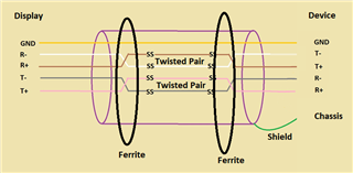
In 2021 because it was RS485 was only 3 wire cable with shield wire.
We are testing both device and display as one set (But actually only device sends messages).
The new display has SP3083.
Now to pass both tests (Radiated and conducted Emission), we are thinking about six options:
1. To disconnect the wires of the receiver of device and wires of the transmitter of display (Because there are no messages), and to remove the ferrites, that will make the tests similar to what have passed in 2021 when it was with RS485 communication.
2. To remove CMC and 10pf from the transmitter of the display and to remove the ferrites.
3. To remove CMC and 10pf from the transmitter of the display and to remove the ferrites and to add CMC and 10pF to the receiver of the device.
4. 1 + Ferrites.
5. 2 + Ferrites.
6. 3 + Ferrites.
What do you think about these options? Please tell me your opinion about each option. And if you suggest another option please tell me about it.
(We should not change the length of the cable)
Hello Sherbel,
Options 1-6 would all be good to test. Removing unused wires will allow less places for emissions to occur and removing the CMC and capacitor will allow provide a good benchmark for the PCB. However, I do not expect each of these solutions to improve the results beyond the previous best test since there are no additional steps or components to change the EMC response.
Go ahead and conduct these tests and share the emissions plots. This will be helpful for further debug. Depending on the results we may have to review the PCB layout.
We checked the CMC in the schematic, and it looks like it is ideal for your current emissions results. Please confirm that 744212100.pdf Is this the correct CMC since the part number is a little different from what is in the schematic.
Best,
Andrew