Other Parts Discussed in Thread: SN74AHC1G125, ISO6762, ISO6740, ISOM8610, SN74AHC1G126
Tool/software:
Hi Team,
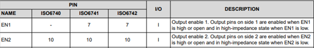
for the ISO6741 in table 6.1 it states the following:
Output enable 1. Output pins on side 1 are enabled when EN1 is high or open and in high-impedance state when EN1 is low. EN2 10 10 10 I Output enable 2. Output pins on side 2 are enabled when EN2
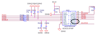
If i have a PWM signal coming from my controller on the digial side of the board this controller is also generating the EN signal,
looking at the table & the device pinout seems that the enable pins are on the wrong side and enforcing me to float the enable signal to the other side.
1) am i reading the D.S correctly?
2) how do you suggest overcoming this issue