This thread has been locked.

If you have a related question, please click the "Ask a related question" button in the top right corner. The newly created question will be automatically linked to this question.

ISO1410: RS485 pin ESD protection features

Part Number: ISO1410


Tool/software:

Hello,

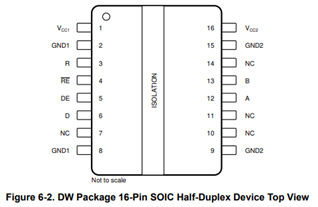
I am using the "iso1410dbw" chip and I did not find on the "iso1410.pdf" datasheet the display of the two pin diagram relating to the two signals A and B (RS485), but only of the D/R, DE and R signals as reported on thedatasheet on page 28.

On other datasheets such as "so15.pdf" the display of the two pin diagram relating to the two signals A and B (RS485) is present (see page 12).

Questions:

- Where can I find for the "iso1410dbw" chip the diagram of the two pins relating to the two signals A and B (RS485) ?
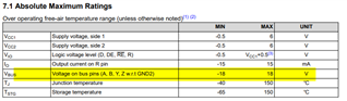
   In particular, I would need to know the electrical characteristics of the protection transils inside (16 V?).

-  Where can I find the differences in the electrical characteristics between the standard "iso1410" version and the "iso1410B" version ?

Thanks for the help.


BR

Demetrio Magrin

  • Hello Demetrio, 

    Thank you for reaching out. ISO1410.pdf is a combined datasheet with the other full-duplex transceivers. 

    ISO1410 uses the pin diagram on page 4 shown below


    ISO1410 is also tolerant of a DC voltage of +/- 18V on the bus inputs shown in the Vbus spec of the absolute maximum conditions in the datasheet. 

    The difference for ISO1410B and reinforced can be found in the following two tables in the datasheet. 

    Best,

    Andrew

  • Hello Andrew,

    thank you for your support.
    I had analyzed the tables you showed me above.
    I needed the electrical characteristics of the protections present on the pins in A and B.
    - Are they zener or transil ?
    -
    What is the maximum current of these zener/transil ?
    -
    Intervention times of these zener/transil ?

    In the application notes it is recommended to add a TVS model CDSOT23-SM712.
    What are the external conditions for having to add this TVS ?

    Thanks for the support.

    BR

    Demetrio

  • Hello Demetrio, 

    The internal protections circuits characteristics are considered TI internal information. They protection circuits will protect against a DC or transient of up to +/-18V. A TVS diode is needed if higher DC voltages are present or if higher voltage transients are expected in the application. 

    Best,
    Andrew