This thread has been locked.

If you have a related question, please click the "Ask a related question" button in the top right corner. The newly created question will be automatically linked to this question.

[FAQ]: What is Surge Immunity per IEC 61000-4-5?

Other Parts Discussed in Thread: STRIKE

What is Surge Immunity per IEC 61000-4-5? How does it affect the communication bus of the isolators? How is it tested? 

  • *Please note that all definitions and references are based on the latest standard IEC 61000-4-5

    Surge immunity for the communication bus

    Definition:

    A surge is a sudden and brief increase in voltage or current in an electrical system or circuit. Surge immunity testing evaluates a devices ability to withstand sudden voltage and/or current transients in a surge event. Its standard is defined by IEC 61000-4-5 which states the testing levels, equipment, setup, procedure and format of the test result.

    Why is surge immunity important in isolated systems and how does it affect the communication bus?

    During a short-lasting surge event, such as a lightning strike, it’s vital that the isolator is able to maintain its isolation barrier until voltage returns to a normal level. For the communication bus, high surge immunity allows the isolator to maintain signal integrity without loss of function or performance degradation.

    Test Levels

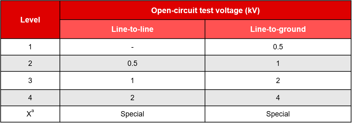
    The surge immunity test is conducted successively at levels 1-4 with the option of adding additional levels above, below, or in between the others. Level 1 represents the lowest required test with a line-to-ground voltage of 0.5kV while level 4 represents the highest with a voltage of 4kV.

    Test equipment

    Simplified circuit of wave generator

                                             U – High voltage source                                                                 Rs – Impulse duration shaping resistors

                                             Rc – Charging resistor                                                                    Rm – Impedance matching resistor

                                             Cc – Energy storage capacitor                                                       Lr  – Rise time shaping inductor

    There are two types of combination wave generators specified in IEC 61000-4-5. The 10/700µs generator is used to test ports that would connect to outdoor symmetrical communication lines while the 1.2/50µs generator is used in all other cases. TI utilizes the 1.2/50µs wave generator in its tests for isolators.

    The 1.2/50µs generator generates the following surge waveforms with the parameters:

     Open circuit voltage: 1.2/50µs


    Front Time:       Tf = 1.67 x T  = 1.2µs ±30%

    Duration:           Td = Tw          = 50µs  ±20%

    Short circuit current: 8/20µs

    Front Time:       Tf = 1.25 x Tr   = 8µs    ±20%

    Duration:           Td = 1.18 x Tw  = 20µs ±20%

    The following equipment is used in the test setup:

    • Device under test (DUT)
    • Cables
    • Coupling/decoupling networks (CDNs)
    • Combination wave generator (CWG)

    Test setup & procedure

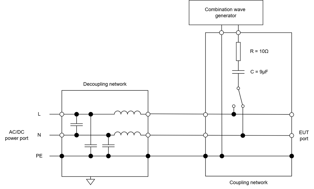
    The 1.2/50µs generator is applied to the DUT logic port via the capacitive coupling network as shown in the figure below. Decoupling networks are required to avoid negative effects on equipment not under test but powered by the same lines.

    Example of line to ground coupling

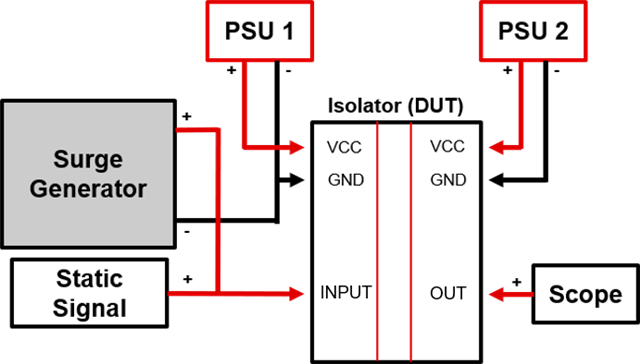
    Starting at level 1, the surge generator strikes the logic port while the signal generator is passing a signal through it. The operator monitors the scope to capture any functional loss or device failure. At each level, the device is struck with 5 positive impulses and 5 negative impulses. For AC strikes, each impulse is tested at 0°, 90°, 180°, and 270°. The time between successive impulses must be 1 minute or less. It is considered a pass if the DUT/EUT withstands all successive pulses at a certain level. For a component level test, the generator utilizes DC strikes.


    Example schematic of ISOxxxx under test:


    Test results

    The test results are evaluated by classifications of function loss or part degradation, and performance level defined under test levels section above. The classification of function loss or part degradation are tabulated below:

    The overall test results are listed as:

    ISOxxxx passes level 4 at criteria A

    Which means, ISOxxxx withstood ±4kV strikes without any loss of function or degradation of performance.


    For surge testing across the isolation barrier refer to: e2e.ti.com/.../faq-what-is-surge-isolation-voltage-viosm