A related question is a question created from another question. When the related question is created, it will be automatically linked to the original question.
If you have a related question, please click the "Ask a related question" button in the top right corner. The newly created question will be automatically linked to this question.
*Please note that all definitions and references are based on the latest standard CISPR 32
Radiated Emissions (RE)
Definition:
RE is the undesired electromagnetic (EM) energy emitting from a device and/or system into the surrounding environment. RE testing consists of measuring the amount of EM energy emitted by a device/system to ensure that it does not emit an excessive amount that could interfere with other devices or systems, or cause harm to people and the environment. The tests standard is defined by CISPR 32 which states the equipment, measurements, test results format, and use of the RE measurements.
Why is radiated emissions important in isolated systems?
During its operation, it is important that the isolator does not cause harmful electromagnetic radiation (EMR) that inhibits the performance of other electronic devices or systems. Harmful EMR can cause data errors, loss of signal in wireless communication systems, and equipment damage leading to system failure.
Test level & equipment
Test levels at frequencies up to 1GHz (Top) and above 1GHz (Bottom) for class B equipment
The radiated emission test is conducted at frequency ranges above 1GHz and below 1GHz. At TI, we typically test in ranges of low frequencies (30MHz – 1GHz) and high frequencies (1GHz – 6GHz). The equipment used in the test is listed below:
Anechoic chamber
Device under test (DUT)
Receiver antennas
Power supply for device (if applicable)
Other appropriate equipment
Test setup & procedure
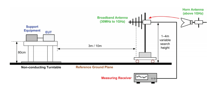
Setup for RE tests above 1GHz and below 1GHz
The DUT is placed on a non-conductive table within the uniform field area at a height of 0.8(±0.05)m. For low frequencies (30MHz – 1GHz), the antenna is set 10m away from the DUT with a piece of anechoic material separating the two. The antenna is configured for horizontal and vertical polarizations and is adjusted in height between 1m – 4m with step size of 1.5m. For high frequencies (1GHz – 6GHz), the antenna is set 3m away from the DUT also with a piece of anechoic material separating the two. The antenna is configured for horizontal and vertical polarizations and is adjusted in height between 1m – 2m with step size of 1m. This setup can be seen above.
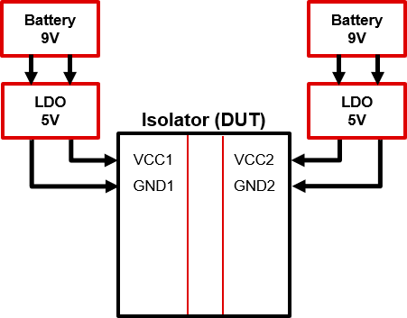
Example schematic of ISOxxxx under test:
Test Results
The test results are evaluated graphically against the field strength average and peak of the given equipment class level. See example below.