This thread has been locked.

If you have a related question, please click the "Ask a related question" button in the top right corner. The newly created question will be automatically linked to this question.

ISO1540: Isolating LIN bus nodes, at +12V violates Absolute Maximum Ratings

Part Number: ISO1540
Other Parts Discussed in Thread: ISO1541, , ISO7741, SN65HVDA100, ISO7841, TLIN1029-Q1, ISO7721, ISO1042, ISO7742, LP2951-Q1, ISOW7841, SN6501

After reading the post Operational Principle of a Bidirectional Isolator (for LIN and I2C Interfaces) by Thomas Kugelstadt, I was rather surprised to discover, that neither the two referenced isolators (ISO1540 and ISO1541), nor any other isolators in the TI portfolio allows bus (or supply-) voltages above 5V (nominal).

This means that none of the isolators are actually suitable for use on the LIN bus - a bidirectional open collector bus, with pull-up resistors typically connected to a +12V supply. Although very similar in electrical characteristics to the I2C/TWI bus, the supply voltages makes all the difference in support parts availability.

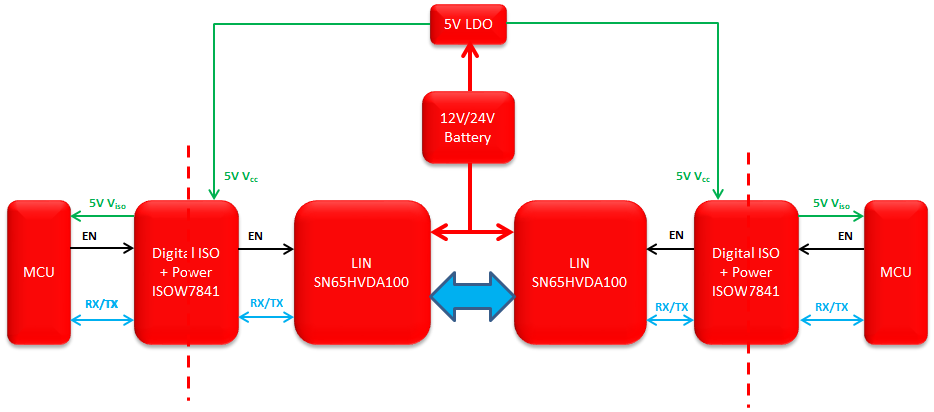
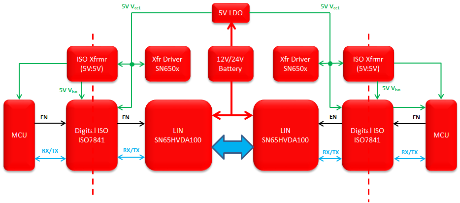
Although the ISO1540 and other isolators could possibly play a part in a LIN bus isolation circuit, by isolating the digital MCU side of the LIN bus transceivers (isolating RX, TX, EN), this solution would still require jumping through hoops to stay within the isolator Absolute Maximum voltage ratings of 6V, and the isolation would still not be optimal. Also, none of the LIN transceivers have native isolation support.

Is it a due to the LIN bus' automotive roots that no isolation circuits are available? While most automobiles does have a common ground (chassis), isolation of the LIN bus would still be beneficial, or even crucial, to overcome ground loops and connecting vehicle elements (e.g. tractor + trailer), where high potential differences may exist.

Is there any "best practice" for isolating segments of - or nodes on - the LIN bus, or would it require piecing the components together from discrete isolator parts?

Any help would be appreciated.

  • Hi Morten,

    Welcome to the E2E forums! Thank you for posting your questions here.

    It is correct that our digital isolators are not meant for direct 12V-supply applications, and TI does not offer isolated LIN interfaces in a single package at this time. As you noted this means isolating a LIN system involves a bit of a more sophisticated design. Two LIN transceivers (like the SN65HVDA100 or TLIN1029-Q1) interfacing with high voltage nodes in the circuit can be used in with isolators (e.g. ISO7741 or ISO7841) between the transceivers and controllers to isolate a LIN system. A block diagram for this idea can be found on the E2E thread here: e2e.ti.com/.../562404

    It is not due to automotive roots that this isolated interface is not available; as a matter of fact the CAN interface, also with automotive roots, can be isolated using a combination of CAN transceiver and isolation (TCAN1042 + ISO7721) or with one chip, the ISO1042. The difference is that the CAN devices support high common mode voltages and read the differential voltage between lines, which is ~3.3V. LIN requires pull-ups directly to the 12V car battery, which TI's portfolio does not support.

    There is not necessarily a best practice given TI's device limitations, but a system may be designed using discrete devices as mentioned earlier or using a 5V regulator between 12V lines and pull-up resistors to protect the digital isolators. I am glad to help you design a system with the available approaches. What kind of LIN solution are you looking to make? Are there crucial parameters or specs you need considered?

    Please let us know the information you have and we'll get started.


    Thank you for your time,
    Manuel Chavez

    PS. If there is any confidential information you would like to share, please note that on your response and we can exchange it directly (outside of this public thread).

  • Hi Manuel,

    Thank you very much for your reply, and for confirming, that TI currently has no dedicated isolators suitable for use on the LIN bus.

    I would continue with a design,locating the isolation circuit between the LIN bus transceiver and the controller logic (operating at 5V), like you proposed:

    My only question is what would be the simplest/cheapest way to provide a suitable VCCx (5V) for the LIN bus side of the ISO774x/ISO734x isolator from the LIN bus power, which is nominally +12/24V range. Any suggestions for a suitable, low-cost regulator (input +7.5 - 24V, output +2.25 - 5.5V) supplying up to 5 mA, which seems to be the maximum operating current (ICC2) of the ISO7742, ISO7342, when operating at DC (or 20 kHz frequency – LIN bus maximum).

    Any design/component choice suggestions would be appreciated.

  • Morten,

    You're welcome! I apologize for the delay, but I will take some time to provide a reliable regulator recommendation and follow up comments on this system. Please expect my reply here on Monday or Tuesday.


    Thank you for your time,
    Manuel Chavez
  • Hi Morten,

    The most cost-effective regulator on TI.com with the parameters listed is the LP2951-Q1, which is automotive qualified – is that a requirement for this system? That leads me to say there is a choice of paths one can take to isolate the power for side two of the isolators and both microcontrollers. The LDO will have different current requirements for each of these approaches and alone does not isolate power.

    Depending on this system’s architecture an integrated power and digital signal isolator like the ISOW7841 can be used where the ISO7741 is in the block diagram, or the power rail can be isolated separately using a transformer driver like the SN6501 (150mA primary side current output) or the SN6505 (up to 1A primary side current output). Please refer to the example diagrams below.


    Isolated LIN + ISOW7841 System

    Isolated LIN + ISO7841 + SN650x System

    How many LIN nodes will be in this design? Is there a diagram you would like to build on? These approaches can be replicated for each node or modified to branch out from one 12V to 5V regulator and optimized.

    My apologies again for the delayed response; please let me know your comments and questions.


    Best,
    Manuel Chavez

  • Morten,

    To showcase how versatile the design possibilities for this system are I'm including an additional block diagram for the ISOW + LIN system with an LDO at each LIN node, which is typical in cars.


    Hopefully all the diagrams and colors aren't overwhelming!


    Sincerely,
    Manuel Chavez

  • Hi Morten!

    Hopefully all is well. Have you advanced this design? If you have questions or concerns feel free to respond to this post!


    Best,
    Manuel Chavez
  • Hello Mortin,

    Since it has been a few weeks since your last response I will close this thread. Please feel free to reply here or ask a new/related question using the yellow and red buttons in the top right corner of this window!


    Happy engineering,
    Manuel Chavez