This thread has been locked.

If you have a related question, please click the "Ask a related question" button in the top right corner. The newly created question will be automatically linked to this question.

ISOW7841: ISOW7841 breaks down

Part Number: ISOW7841
Other Parts Discussed in Thread: TIDA-00300

Hello, this topic is a continue of a previous one ISOW7841: ISOW7841 breaks down

The same customer has some additional questions:

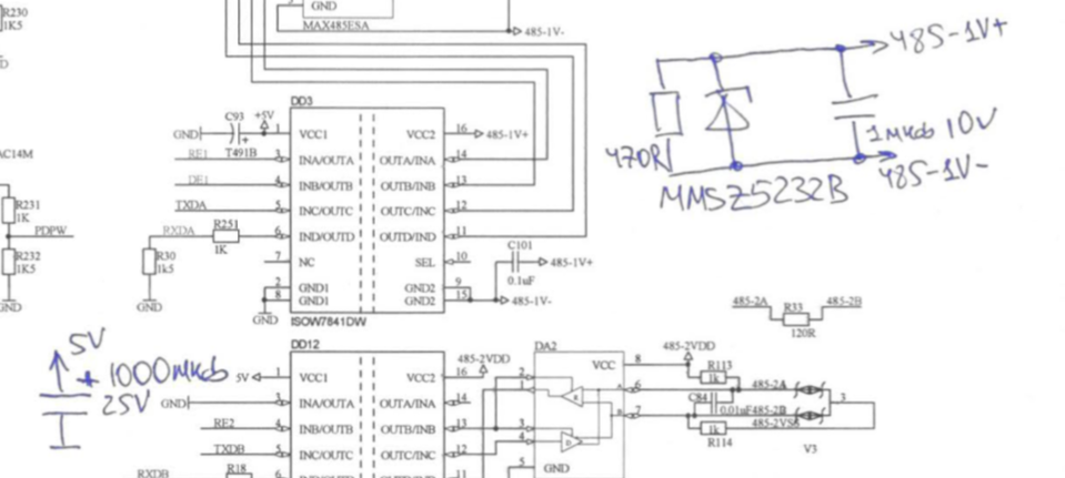
1. In TIDA-00300 design the output of ISOW7841 is protected by zener diode. But such solution is not described in data sheet. Is it mandatory to place a zener diode to protect ISOW7841?

2. In customer's application ISOW is used for different interfaces (485, CAN, RS-232).

The current consumption from internal voltage converter of ISOW is not continuous, but changed in a pulsed way, because of used interfaces specialities.

Unlike TIDA-00300, customer's design does not contain an LED on ISOW output. This LED acts also as a passive load for internal power converter in ISOW.

Could be happen, that these two factors (pulsed current, lack of additional passive load) can lead to voltage increasing, when interface stops to consume the current?

  • Hi Slava,

    Thanks for reaching out to us. Please find below my inputs.

    1. TIDA-00300 has implemented an optional additional overvoltage protection using Zener diode, this is not mandatory for ISOW. But to avoid any such overvoltage issues, please do follow the recommendations provided in the E2E post that was posted by Andrey.
    2. Understood.

    Pulsed current is not going to be a problem for ISOW, the current need not necessarily be continuously drawn.

    The passive load is also not a mandatory requirement if the suggestions provided in Andrey's E2E post are followed.

    We don't expect the pulsed current operation and lack of passive load to cause any overvoltage problems. The overvoltage issue can occur if the primary supply of iSOW VCC, goes through brown-out while the secondary side supply VISO stays above its UVLO. Such test condition may result into sync issues between primary and secondary dice thereby leading to an open-loop operation eventually resulting into output overvoltage condition. Thanks.

    Regards,
    Koteshwar Rao

  • Hi, Koteshwar.

    Customer upgraded his board:

    - 1000uF capacitor on VCC rail is added

    - 1uF capacitor, 470R resistor and zener diode are added in parallel to VISO bus

    Then customer performed a power cycle tests with watching for VCC(blue) and VISO(yellow).

    As we can see on the scope below:

    - in some cases after VCC is applied (blue), VISO(yellow) starts to increase

    - increasing of VISO(yellow) happens, while VCC voltage stays stable(blue)

  • Hi Slava,

    Thank you for sharing the update with waveform.

    Could you please confirm the capacitors used at VISO pin? I see you mentioned that customer added 470Ω resistor, Zener and 1µF capacitor. Is this in addition to the capacitors that were already existing? Could you please confirm what were the already existing capacitors?

    VCC & VISO need a min of 10µF + 0.1µF as close as possible to the pins on the same PCB layer as device. Any value less than 10µF + 0.1µF will make the device not operate normal. That's why I needed a confirmation on this.
    It is suggested to use an additional 100µF at VCC to avoid any overvoltage issue due to power cycle tests. Please do also point out where exactly was the 1000µF capacitor placed on customer PCB? Any pictures showing the placements would also be helpful.

    Please do confirm that these suggestions for capacitor values and their placement are followed. Thanks.

    Regards,
    Koteshwar Rao

  • Hi, Koti.

    Customer performed some additional tests and found the point, where ISOW works stable.

    The following components were placed as close as possible to ISOW:

    - Viso - 0.22uF + 15uF + 470 Ohm + Zener

    - Vcc - 0.22uF +15uF

    With total capacitance of all installed capacitors on Vcc bus on board is equal to 1150 uF, overvoltages on Viso side continue to appear.

    After total Vcc capacitance were decreased to 450uF, Viso get stabilized.

    50 cycles of power test did not lead to any abnormal behaviour.

    Now customer is going to perform tests with small serie of boards in temp range -40...+50 C.

  • Hi Slava,

    Thanks for the update and glad to know that customer is able to find the capacitance values where ISOW works fine.

    We expect ISOW to work without any issues for the values of capacitors where capacitor at VCC is at least 100µF larger than the capacitor at VISO, provided these capacitors are placed close to device power supply pins and the smaller value capacitors (preferably 10µF + 0.1µF) are placed the closest to device power supply pins. To make sure these recommendations are followed, would you be able to help me with the schematic and PCB layout of customer test board? You could also send me these files over email. Let me know if you have any questions, thanks.

    Regards,
    Koteshwar Rao

  • Hi Slava,

    Please do help us with the requested information in my previous post. Thanks.

    Regards,
    Koteshwar Rao

  • Hi,

    The discussion has moved to emails and is going to take longer time for evaluation. I will close this thread due to inactivity here and will come back to post an update if the thread is not locked out. Thanks.

    Regards,
    Koteshwar Rao