This thread has been locked.

If you have a related question, please click the "Ask a related question" button in the top right corner. The newly created question will be automatically linked to this question.

ISO7740-Q1: Output current

Part Number: ISO7740-Q1
Other Parts Discussed in Thread: OPA4170, ISO7740

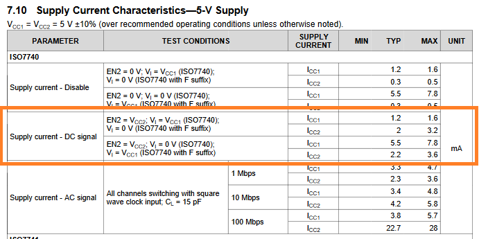
Does the ISO774x-Q1 family limit output current? The tables and graphs would indicate that it does not because they allow for high currents. I have a potential case where the circuit exceeds the absolute maximum values of ±15mA.

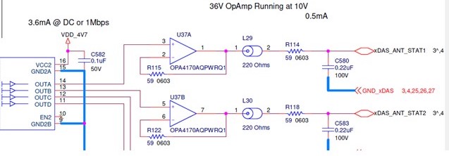
I am trying to simulate a circuit where the output from an ISO7740-Q1 feeds the input of an OPA4170 op amp. Because of the design of the circuit, the simulation shows peak output currents of ±28mA.

TI told me, in a separate post, that these currents can occur if the device driving the op amp input has a fast rise/fall time and is not current limited.

Additional data:

Vcc1 of ISO7740-Q1 is 3.3V. Vcc2 is 5V supply. The output feeds directly into positive input of op amp (no current limiting resistor). The op amp has a 59 ohm feedback resistor and a load of 59 ohms in series with a 220pF cap. I don't have a simulation model for theISO774x-Q1 family, so I am using a simple voltage source.

  • Hi William,

    Thank you for posting to E2E!

    Digital isolators do not include output current limiters since most connections on digital lines have high input impedances.

    In this case, OPA4170 has a very high input impedance (10E12 Ohms), so current-limiting resistors will not be necessary if using it as a buffer.

    Can you share a schematic of your system and an image of the simulation circuit? How fast did the rise/fall times have to be to cause this increase in peak output currents from the OPA4170??


    Please expect our follow up response during business hours M-F.


    Have a great weekend,
    Manuel Chavez

  • This is from the OPA4170 folks: OPA4170-Q1: Input current in simulation

    In essence, the input impedance doesn't matter under certain conditions because there are diodes that become forward biased for a short duration.

    I used the rise/fall times specified in the ISO774x-Q1 datasheet. I haven't looked at how slow the transition must be to reduce the currents. I do know that 1k resistors for work for the feedback and as a limiter on the ISO7740-Q1 output.

  • I also have follow up questions:

    1) Specified supply currents are for all four channels combined or per channel? Based on the way the datasheet reads, I'm guessing combined.

    2) Given that the design I'm trying to analyze has dual supplies, do I simply divide by two to get supply current for nonisolated side vs isolated?

    3) The channels are designed such that two are always high input and two low input, so I would average the high/low supply currents, correct?

  • Hi William,

    Thank you for sharing the amplifiers thread and your schematic. Given the buffer is a G = 1V/V scenario, I agree that adding 500Ω - 1kΩ resistors in series with the isolator outputs will limit current to <10mA in Vcc2 = 4.7V operation. 1kΩ  resistor values and greater may be a more reliable option to prevent the internal protection diodes from turning on at the expense of noise performance.

    Regarding your follow-up questions, the current consumption values are specified for all channels being subject to the same input. The current per isolated supply is broken up as "Icc1" and "Icc2," where Icc1 is the current consumed by the input side of an ISO7740 and Icc2 is the current consumed by the output side. For this case where the inputs are 2 LOW and 2 HIGH, an estimate can be made as:

    Icc1_max ~= 1.6mA/2 + 7.8mA/2 = ~4.7mA

    Icc2_max ~= 3.6mA/2 + 3.2mA/2 = ~3.4mA

    For a total current consumption of ~8.1mA using the datasheet table below:


    Thank you,
    Manuel Chavez