This thread has been locked.

If you have a related question, please click the "Ask a related question" button in the top right corner. The newly created question will be automatically linked to this question.

ISO7841: ISO7841 voltage pressure problem

Part Number: ISO7841
Other Parts Discussed in Thread: ISO7840,

Hi 

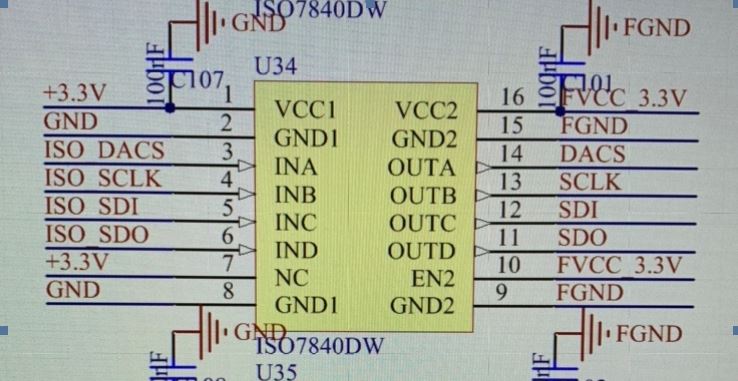
At present, 2 ISO7841 and 12 ISO7840 are used. During a certain normal output, 2 ISO7841 are damaged, and some pins are short-circuited to ground, which is suspected of withstand voltage. Our design refers to the following picture.

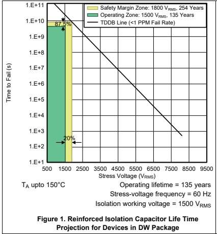
As shown in the figure below, it can reach a service life of 3 years under 2500V
1. According to the usage scenario in the above picture, whether the above chip is in accordance with the design under 2400V isolation voltage (usually used for pulse output and will not always work at 2400V), is there any technical risk;
2. The problems are all with ISO7841, whether it is different from ISO7840;
3. This chip claims that the withstand voltage can reach a voltage of 8000Vpk, which is quite different from the actual voltage used. How should we look at this part, or directly evaluate the isolation voltage and life according to the above figure;

  • refer picture as below

  • Hi Pei,

    Sorry to hear about the issue. To better comment on the issue, could you please help me with the below information?

    1. What is the application and how are ISO7841 and ISO7840 used in the application?
    2. A schematic and/or a block diagram would also help me understand the usage of isolator better.
    3. Please also explain what is the working voltage requirement? Working voltage is the continuous high voltage that is present in customer application continuously. For example, the DC bus voltage of a motor drive system is considered as working voltage.
    4. If there is no continuous high voltage in system then please do let me know why does customer need 2400V working voltage?

    Though the TDDB plot provides a good relationship between stress voltage and lifetime, please note that this data not to be used as is and necessary margins to be considered. Considering such margins, ISO78xx in DW package supports 1500Vrms as working voltage as claimed in the datasheet and hence, we do not officially support 2400V.

    With that said, if I can understand the nature of high voltage stress expected in customer application then I will be to comment if the device is expected to support customer requirement, though we still won't be able to officially guarantee anything outside of datasheet but can give our comments / guidance if the device will be able to handle customer HV requirements. Let me know, thanks.

    Regards,
    Koteshwar Rao

  • Hi Rao

    Thanks for your response, you can refer below answers:

    1.Application: Floating power supply design with 2200V (DC) output capability, ISO7840 and 7841 are used to transmit some common ground control signals to the floating end; when our equipment outputs 2200V voltage (DC), the voltage across the ISO7841 and 7840 will be Reached 2200V;

    2. schematic as below:


    3. When equipment outputs 2100V voltage, the voltage at both ends of ISO7841 and 7840 will reach 2100V; the normal state is that the voltage at both ends is 0V

    4. Equipment will not have continuous high voltage, but there will be a maximum pulse output of 2200V, such as 2200V outputting 100ms per second, consider a certain margin, so we choose 2400V for experimental shock.

  • Hi Pei,

    Apologies for the delay in response and thank you for sharing the requested information. This helps me understand the application better.

    I understand that the application is high voltage isolated power supply where the isolator is sitting between the two sides of the isolated power supply. You also mentioned that HV of 2200V will be present for 100ms per second which is equivalent to an AC with 10% duty cycle. Since such 10% duty cycled HV is being observed by the isolator periodically, this is considered as a continuous voltage.

    In other words, the non-continuous voltage usually refers transients that usually happen for a few ns or µs and do not periodically repeat. Everything else is to be treated as continuous voltage.

    Hence, it seems like the device spec are being exceeded by your application. I would recommend considering ISO7840 / ISO7841 in DWW package which supports 2kVrms / 2.8kV DC of working voltage. This gives sufficient margin to your application to be considered safe.

    The issue that customer is observing may or may not be related to the exceeding HV ratings. Hence, I need more information for me to be able to under the issue better.

    1. I would require a larger schematic showing the entire application.
    2. I would also need you to describe the exact information related to failures.
      1. Which pins of device are shorted to GND?
      2. When does customer see the device fail? Is it immediately after power up, or after running it for many hours? Or does this happen during any other EMC tests?
      3. Knowing at what instant the failure occurs is necessary to debug the issue faster.
      4. How many devices tests and how many failures observed?

    Please do help me with the requested information to debug the issue faster. If you cannot share the schematic on E2E, then you can send me an email. Thanks.

    Regards,
    Koteshwar Rao

  • Hi Pei,

    Please do share the information related to the issue as requested in my previous post to be able to debug further. Thanks.

    Regards,
    Koteshwar Rao

  • Hi Pei,

    Hopefully customer has identified the cause for device failure. I will go ahead and close this post, if the issue is unresolved please do respond to this post. Thanks.

    Regards,
    Koteshwar Rao