This thread has been locked.

If you have a related question, please click the "Ask a related question" button in the top right corner. The newly created question will be automatically linked to this question.

ISOW7841:About VCC current

Part Number: ISOW7841

Hello experts,

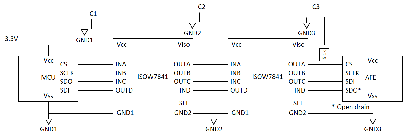
I used ISOW7841 at VCC = 3.3V, VISO = 3.3V and connected 510Ω as a VISO load.

Vcc and VISO are connected to 10uF and 0.1uF respectively.

The Icc at that time is 270 mA with a pulse width of 3 us and repeats in 15 to 25 us cycles.
Is this a normal current waveform?

Best regards,

  • Hi user62646671,

    Yes, this is expected peak current. If you would like to reduce the peak current then you can either use a series ferrite bead that limits the peak current or reduce output decoupling capacitors from "10uF + 0.1uF" to "3.3uF + 0.1uF". You can also do both of these options which should definitely reduce the input peak current. Let me know the resuojce you try these experiments. Thanks.

    Regards,
    Koteshwar Rao

  • Hi, Koteshwar

    Thank you for your reply.

    I would like to check the current when the output decoupling capacitors are reduced.

    In addition, I am thinking of double-insulating SPI communication using two ISOW7841 as shown below. Please tell me the optimum value of the C1-C3 capacitor in this circuit.

    Best regards,

  • Hi,

    The decoupling capacitors for each ISOW device should be independently provided and also placed within 2mm distance from its power supply pins, Hence, each ISOW7841 device should have 10µF + 0.1µF at VCC and 3.3µF + 0.1µF at VISO. Therefore, you would have to replace C2 with two sets of resistors (10µF + 0.1µF at VCC and 3.3µF + 0.1µF).

    Let me know if you have any other questions, thank you.

    Regards,
    Koteshwar Rao

  • Hi, Koteshwar

    Thank you for your reply.

    I would like to check the operation with these recommended capacitors.

    Best regards,