Other Parts Discussed in Thread: ISO1412, ISO1042
Hi Tech Support Engineer:
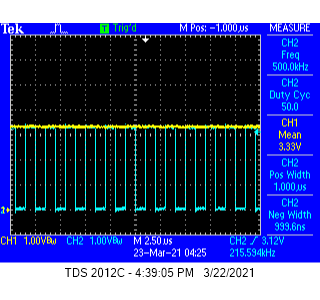
I received the ISO1412DWEVM kit today and was testing the output
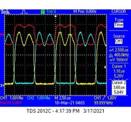
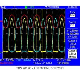
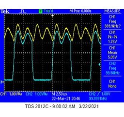
and seeing an 400kHz ripple superimposed on the output (Y, Z) instead of a DC that expected
Please see pictures attached.
Is this normal??
Regards
Kai

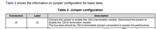


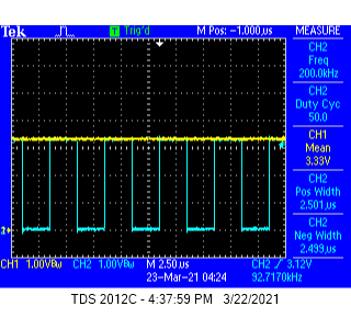
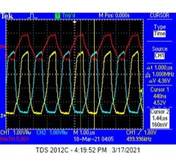
 200K Hz, Vcc2, Y Termination Jumper ON
 200K Hz, Vcc2, Y Termination Jumper OFF
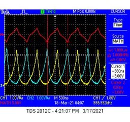
 300K Hz, Vcc2, Y Termination Jumper ON
 300K Hz, Vcc2, Y Termination Jumper OFF
 400K Hz, Vcc2, Y Termination Jumper ON
 4
4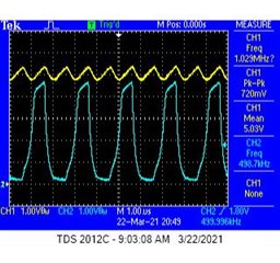 500K Hz, Vcc2, Y Termination Jumper ON
 500K Hz, Vcc2, Y Termination Jumper OFF
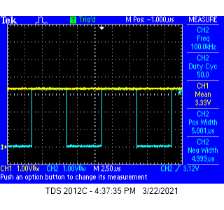
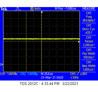
 100kHz Vcc2 Y Jumper is ON.
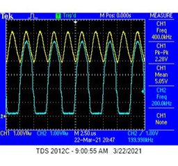 2
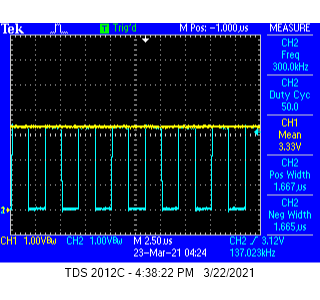
2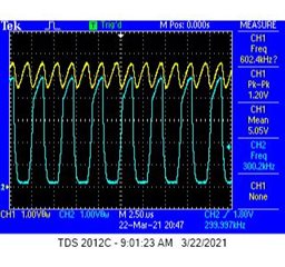 300kHz Vcc2 Y Jumper is ON.
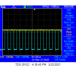
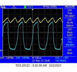 400kHz Vcc2 Y Jumper is ON.
 500kHz Vcc2 Y Jumper is ON.
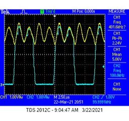 1
1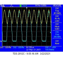 200kHz Vcc2 Y Jumper is OFF
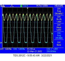 300kHz Vcc2 Y Jumper is OFF
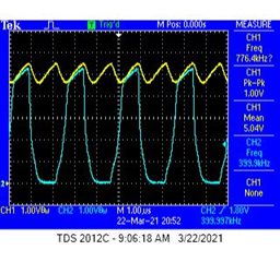 400kHz Vcc2 Y Jumper is OFF
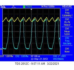 500kHz Vcc2 Y Jumper is OFF
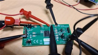
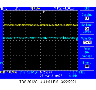
 Vcc stays Solid ON.