This thread has been locked.

If you have a related question, please click the "Ask a related question" button in the top right corner. The newly created question will be automatically linked to this question.

SN6505A: Request a Review the Design of SN6505A

Part Number: SN6505A
Other Parts Discussed in Thread: SN6505B

Hello

We inquire about the application of the SN6505A for below design.

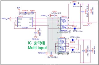
1.Is it available to connect two transformers in parallel? if available, could you review the design?
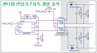
2.Is it available the secondary side of the transformer be separated and used? if available, could you review the design?
3.What can I do to reduce EMI? Could you provide reference design for reduce EMI?

Best regards

  • Hi Louis,

    Thanks for reaching out. Please see my inputs below,

    1.Is it available to connect two transformers in parallel? if available, could you review the design?

    Yes, two transformers can be connected together to get two separate outputs provided the total input current required by the two transformers doesn't exceed SN6505A current rating.
    I couldn't find datasheet for the transformer YETRF0907H-ST / T-YETRF0907H-ST, could you please share the datasheet to review?

    2.Is it available the secondary side of the transformer be separated and used? if available, could you review the design?

    Yes, this is also possible. Transformer can have multiple output windings to generate multiple output rails. Please see below application note for examples.

    https://www.ti.com/lit/slla436

    3.What can I do to reduce EMI? Could you provide reference design for reduce EMI?

    We usually don't hear from customer about SN6505 causing any EMI challenges for any industrial applications. One of the ways to reduce emissions further is to lower the switching frequency. By choosing choosing SN6505A (160kHz) over SN6505B (420kHz), you are already lowering emissions even further. Hence, just using SN6505A should be sufficient to meet your emissions requirement. Thanks.


    Regards,
    Koteshwar Rao

  • Hi Koteshwar

    Thanks for your support.

    We have a additional inquiry.

    In the datasheet, recommendations for bulk capacitors at the rectifier output are marked from 1uF to 10uF. 

    However, is it available to exceed 10uF as shown in the circuit below?

    Best regards

  • Hi Louis,

    Thanks for sharing additional details.

    Higher capacitance at the output will lead to higher inrush current during power up. May I know what are the output voltage and current requirements? If the output current requirement isn't much then the capacitors you have used should not be an issue, except that it will have higher input inrush current during power up.

    i am also not very sure if the Zener regulator is correctly implemented. I right now see that Zener diode is in series path and hence might not work like a regulator.

    Let me know if you have any further questions, thanks.


    Regards,
    Koteshwar Rao