This thread has been locked.

If you have a related question, please click the "Ask a related question" button in the top right corner. The newly created question will be automatically linked to this question.

ISO1430: A and B voltages

Part Number: ISO1430

I have a design using a ISO1430BDWR 485 Isolator.
I'm already testing the chip using boundary scan to exercise the R, /RE, DE, and D lines.
I'd like to test the A and B lines at the connector on my board. Due to the complexity of the controlling firmware, I'm unable to just send or receive an RS-485 message.

Testing the chip itself is completed, but now I want to test the connector where my A and B lines leave the board.
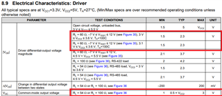
I have the ability (through boundary scan) to set the A and B lines (by setting the TXD line). I was thinking about setting TXD High, reading the voltage between A and B, and then setting TXD Low, and measuring the voltage again. I would expect the voltage to be positive for one reading, and negative for another. I'm having trouble finding what that voltage should be.

I have 3.3V going to VCC1 on the chip, and 3.3V (Isolated) going to VCC2. I need to document why the level is what should be expected either by having a reference document or an equation.

Thank you.

  • Hi Matt,

    Thank you for reaching out to us.

    Base on the datasheet section 8.9. The Vod_min is 1.5V, and the Vod_typ is 2.3V for RL = 60 ohm.

    The common-mode voltage is Vcc/2. The equation to calculate the voltage for bus A and B is as follows.

    Vcc/2 - Vod_typ/2 <= Low voltage range <= Vcc/2 - Vod_min/2

    => 0.5V <= Low voltage range <= 0.9V

    Vcc/2 + Vod_min/2 <= High voltage range <= Vcc/2 + Vod_typ/2

    => 2.4V <= High voltage range <= 2.8V

    Regards,

    Alfred

  • My circuit does not have a resistor connecting A and B.  I'm using the values for the Open Circuit Voltage in Row 1 of the table in 8.9.  Since my Vcc2 is 3.3VDC, is VOD_Typ  still 5? 

    When I measure the outputs with a DMM, I get the following:

    TXEN = 1
    HIGH (TX)
    Ground to A 1.268
    Ground to B 0.535
    A to B -0.731
    LOW (TX)
    Ground to A 0.002
    Ground to B 0.73
    A to B 0.728


    These numbers do not make sense given your previous response.

  • Hi Matt,

    Section 8.9 specified the condition is Vcc1=3.3V and Vcc2=5V unless otherwise noted.

    Hence, the 5V is for Vcc=5V unloaded bus. For Vcc =3.3V, the Vod should be 3.3V.

    For High TX, the expected A-to-ground voltage is 3.3V unloaded, and the expected value B-ground is 0V.

    Also, RS-485 is a symmetrical bus that pins A and B should both swing from 0V to 3.3V unloaded.

    From your data, pin B voltage only goes from 0.5V to 0.73V and it did not make the same transition as

    pin-A from 1.268V to 0.002V. It seems to me the bus is either loaded or shorted.

    Could you please share the schematic of your design?

    Regards,

    Alfred

  • Hi Alfred.  Is there a way I can share it privately?

  • Hi Matt,

    We will take this discussion offline as we are communicating confidential information.

    We will update the post after we have a solution.

    Regards,
    Alfred

  • Alfred, 
    As you pointed out, I had a bidirectional diode in my circuit that was causing these voltage levels.
    Once I removed the diode, my A and B voltages were between 0 and 3.3 (with respect to ground).  Thank you for your help and quick responses!