This thread has been locked.

If you have a related question, please click the "Ask a related question" button in the top right corner. The newly created question will be automatically linked to this question.

ISO6720: Device failure modes

Part Number: ISO6720

Hi team, 

I'm looking for some additional inputs to go along with the FMEA analysis / datasheet of ISO6720:

In the case where TDDB is exceeded and the isolation fails, is there any scenario where the device would fail short or does the dual cap isolation structure completely prevent this? 

Are there any additional effects (other than affecting insulation lifetime) when the device sees higher than the working voltage? Is there any difference in device function / does operation remain normal up until the isolation fails when seeing a voltage below the max but above the working voltage for extended periods? 

Do you have a function you can share that estimates TDDB at application temperatures rather than worst case scenario as shown in the datasheet?

Thanks and best regards

Dan

  • Hi Dan,

    Thank you for posting to E2E! Please read the white paper and blog post linked below for detailed responses to these questions:

    Understanding failure modes in isolators white paper (SLYY081A):
    https://www.ti.com/lit/wp/slyy081a/slyy081a.pdf?HQS=asc-int-iso-SCBOCT-contrib-whip-null-wwe&ts=1600962188509

    Understanding isolator failure modes for safe isolation blog:
    https://e2e.ti.com/blogs_/b/industrial_strength/posts/understanding-isolator-failure-modes-for-safe-isolation

    In short, all types of isolators can "fail short" if their isolation ratings are sufficiently exceeded, and TI's digital isolators have high isolation ratings to provide customers with plenty of margin for their designs. In cases where isolation ratings are exceeded, but not dramatically, one of the two isolation caps might remain operational preserving limited operation of the isolator.

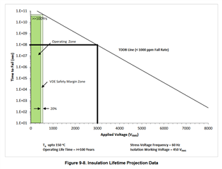
    The TDDB chart in the ISO6720 datasheet, Figure 9-8, shows the lifetime projection data for ISO6720 when different stress voltages are applied across the device's isolation barrier. For example, if 3kV are applied continuously, the isolation barrier is expected to operate for ~3 calendar years:


    In the white paper linked above, a failure mode is discussed where a damaged isolator can sink enough energy to heat the device beyond its maximum temperature ranges, and in this case, the isolation barrier can be degraded. Ensuring the safety-limiting values in Section 6.8 of the ISO6720 datasheet are not exceeded, even during failure conditions, prevents this degradation from occurring.

    More information on safety limiting values, including mitigation examples, can be found in the blog post below:

    Understand and apply safety-limiting values for digital isolators blog:
    https://e2e.ti.com/blogs_/b/analogwire/posts/understand-and-apply-safety-limiting-values-for-digital-isolators


    Please let us know if you have any further questions.


    Thank you,
    Manuel Chavez

  • Thanks Manuel that's just what I needed :) 

    One more question on the same topic - Do we have lifetime test data we can share with the customer showing no short failures below the TDDB line? We have an NDA if this is something you'd like me to email instead of the forum etc

    BR

    Dan

  • Hi Dan,

    You're welcome! One of the PASS criteria for isolation-related tests, including TDDB tests, is ensuring there is no increased leakage current across the isolation barrier after the test -- usually this is a value <10-100uA. Since TDDB tests results are verified with across-the-barrier leakage current measurements,  "short" failures are not expected within the TDDB line.

    More information on this can be found within the document SLYY081A shared above Slight smile


    Respectfully,
    Manuel Chavez