This thread has been locked.

If you have a related question, please click the "Ask a related question" button in the top right corner. The newly created question will be automatically linked to this question.

ISO1050: isolated CAN transceiver design

Part Number: ISO1050

Hi Sir/Madam,

We are using ISO1050DUBR isolated CAN Transceiver for one of my application,

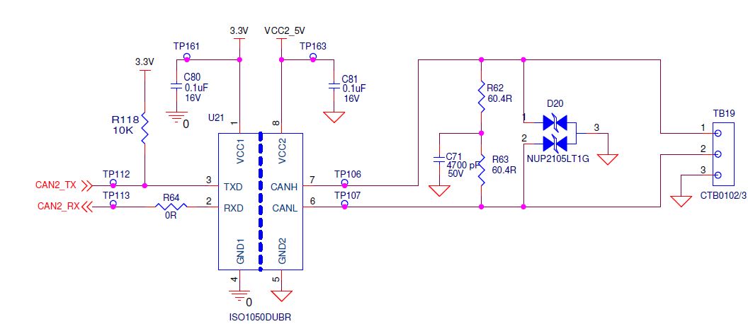
while in the schematic drafting we have a doubt about the requirement of pull up resistor in the TXD line of the transceiver chip to the microprocessor.

we are using BEAGLEBONE BLACK as a control board.

 please confirm this query as soon as possible, so that we can finalize  the schematic.

Image file of the schematic is attached.

  • Hi Nithin James,


    Thanks for the question.


    TXD is very weakly internally pulled up to Vcc1. An external pull up resistor should be used to make sure that TXD is biased to recessive (high) level to avoid issues on the bus if the microprocessor doesn't control the pin and TXD floats. See section 8.3.2 Digital Inputs and Outputs of the ISO1050 datasheet (page 18).


    In the case of the beaglebone black that will be used in your application, I believe you can enable pull-up and pull-down resistors internally on the beaglebone, but this also may be too weak.


    I would recommend using external 10k pullup resistor on TXD as you have done in your schematic.


    If this answers your question for the pullup resistor please click “This resolved my issue.” If not, reply to the thread and I am happy to help you further.


    Thanks and best regards,

    Dan

  • Thanks for replying ,
    We got clarified in the schematic side, now in PCB routing whether we need to consider any differential impedance matching for the CAN signals or not.
    if impedance matching is required can you please suggest how much it is .
  • Always happy to help!

    120Ω differential routing (60Ω single ended) to recommended to match cable/bus impedance. CAN is a relatively slow signaling rate, so impedance matching is not as important as some other applications, but good matching is good design practice.

    Mismatch could cause worse emissions or in worst case - glitches in transmission. I found this application report that shows some examples of what could happen when impedance mismatch occurs (though it focuses spacing of CAN Bus Connections, but you can see how a similar analysis could be done for differential impedance matching).

    Best regards,

    Dan