This thread has been locked.

If you have a related question, please click the "Ask a related question" button in the top right corner. The newly created question will be automatically linked to this question.

ISO7741: ISO7741FDW EFT test failed

Part Number: ISO7741

Dears,

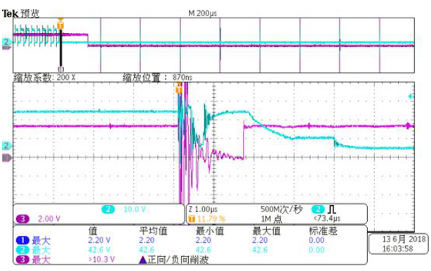
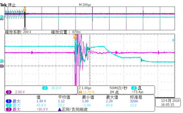
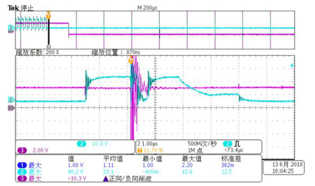
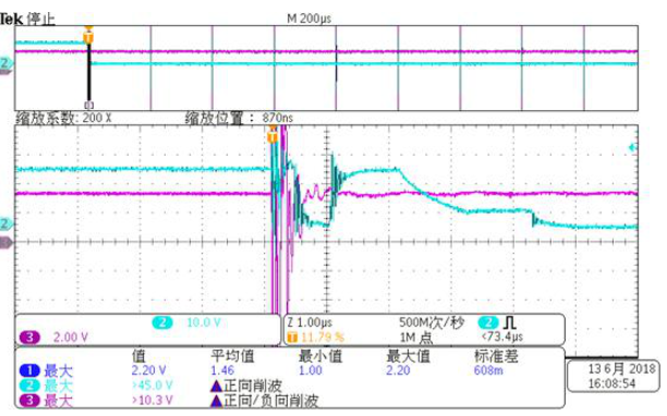
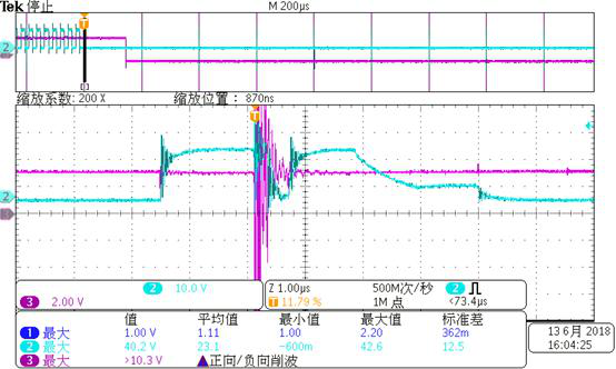
Our customer uses  ISO7741FDW for EFT test, but the result is that the input FAU_A has no low level,but the output FAULT_A of  ISO7741F has about 1us  high level .Below is his test  setup and waveform. Could you please give me some advice?Thank you

Best regards

Kailyn

  • Kailyn,

    Where in the circuit is the EFT being introduced? Also, I'm having trouble reading the scope shots as they are in a different language. I am assuming that the purple channel is FAU_A and the blue channel is FAULT_A. Is that correct? Also, what are the volts per division for each channel?

    Respectfully,
    Lucas
  • Kailyn,

    I haven't heard from you in a while. Were you able to resolve the issue?

    Respectfully,
    Lucas
  • Lucas,

    Sorry to reply you so late. You're right that the purple channel is FAU_A and the blue channel is FAULT_A.  And also I didn't receive the customer's reply. I am so sorry to interrupt you.  Thank you very much.

    Best regards

    Kailyn

  • Kailyn,

    It is ok. I am going to close this thread for now. If you need further help please create a new thread. Thank you!

    Respectfully,
    Lucas
  • sorry for the late reply.

    Previously purchased TI's ISO7741FDW chip, we are now applied to the SiC driver board, but encountered some problems in the pulse group (EFT) experiment, trouble to help analyze, thank you.

    The figure below is the block diagram of the corresponding part.


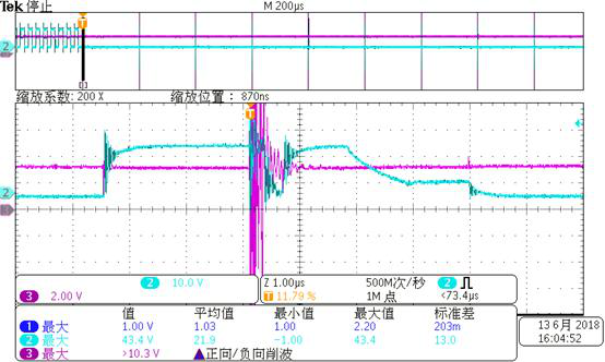
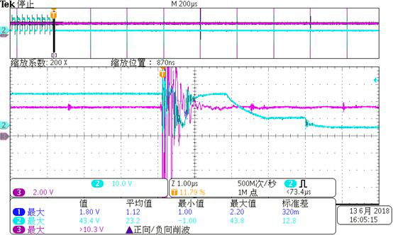
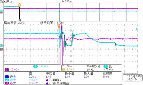
    When doing EFT, the measured waveforms are as follows.

    1. Primary side FAULT_A (3 channels) and corresponding gate output (2 channels)


    2. Secondary side FAU_A (3 channels) and corresponding gate output (2 channels)


    3. Primary side 3.3V power supply (3 channels) and corresponding gate output (2 channels)


    4. Secondary 5V power supply (3 channels, relative to the gate ground, the chip ground is -2V relative to the gate) and the corresponding gate output (2 channels)


    5. Primary side enable (3 channels) and corresponding gate output (2 channels). The enable signal terminal is pulled up to the power supply through a resistor


    As can be seen from the above figures, the signal FAU_A transmitted to ISO7741F is not pulled low at EFT, but FAULT_A from ISO7741F appears low for a period of time. What is the cause of this problem? ? I haven't found the reason yet, so I would like to ask.

  • The waveforms posted appear like they could be OCA and FAULT_A compared to each other. Can you confirm this? Would you be able to provide a scope shot of FAU_A and FAULT_A together? If they are different and FAU_A is noisy, try adding an RC filter to the input of the isolator where RC is much greater than 50ns. Is there any information on the application for the isolator?

    -Lucas
  • I haven't heard from you in a while so I hope you have resolved your issue. If not, please open a new thread and we will continue to provide assistance.

    Respectfully,
    Lucas