This thread has been locked.

If you have a related question, please click the "Ask a related question" button in the top right corner. The newly created question will be automatically linked to this question.

SN6501: Turns ratio, Input current & inrush current

Part Number: SN6501
Other Parts Discussed in Thread: SN6505B

Hi,

I would like to know if I want to get 12V output from 5V input using SN6501 I would require transformer turns ratio of 2.9 (I have not considered LDO at the output) as per equation-10 of the datasheet, I want

to know am I following the right method. I would like to know is there any equation to calculate input current and I would also like to know the inrush current that the device can handle.

  • Hi Kaverappa, and welcome to the E2E forums!

    It is possible to achieve 12V output voltage from a 5V input on the SN6501. The requested equations are explained as follows:

    For any output current load on the secondary side of the transformer, Iout, the input current, Iin, is calculated as
    Iin = Iout x N
    where "N" is the transformer turns ratio

    This means that since the SN6501 can output a maximum current of 350mA @ 5V, the maximum current the device should sink on the primary side is reflected on the output as
    350mA / 2.9 = ~120mA
    120mA on the output. Is this within the expected inrush load current?

    If you have a capacitive load >5uF or require higher current capabilities, please consider the SN6505B.

    Please let me know if this is helpful! I would like to answer all of your questions.


    Thank you for your time,
    Manuel Chavez

  • Hi Manuel Chavez thanks for your response
    ya we have a capacitive load of 990uF, and I was doing the analysis of 5V input to 12V output but they have used 0.38 turns ratio with primary inductance of 538uH.

    I want to know can we achieve 12V output using 0.38 turns ratio with SN6501.
  • Hi Kaverappa! You're welcome.

    A transformer of 0.38 turns ratio (referring to 1 turn on the primary side for every 2.63 turns on the secondary side) will yield an output voltage of about 13V, so the turns ratio is appropriate for this application.

    Whether the specific transformer is compatible with the SN6501 depends on its V-t product. As long as it is >9.1Vus the transformer will not saturate.

    The 990uF load will not work with the SN6501. This will appear like a short on the primary side and is too large for the device to drive, but there is a possible workaround to this which can be implemented in two ways:

    Implement a soft start circuit:

    1. A soft start circuit is necessary for the device to behave appropriately with highly capacitive loads, and an external soft-start circuit can be designed around the SN6501 as described in this E2E post.

    2. Replace the SN6501 with an SN6505B. The SN6505 has soft-start built in and does not require additional components for driving high capacitive loads on the secondary side of a transformer.


    Hopefully this is helpful! Please let me know your transformer's V-t product and whether you would like to design using the SN6505B or an external soft-start circuit.


    Thank you for your time, and happy holidays!
    Manuel Chavez

  • Hi Kaverappa,

    Did you find my previous response helpful? For some clarification on the SN650x and in-rush current, please read the following:

    Based on internal circuitry - metal traces specifically - the SN6501 can momentarily sink 2 - 3 Amps through its D1 and D2 FETs. This means inrush transients are physically limited to ~3A on the primary side of an isolated power supply using the SN6501.

    We strongly recommend using the SN6505 with capacitive loads > 5uF because although the SN6501 can handle excessive currents in *brief* events, the cycling of capacitors over many resets may cause long-term reliability concerns [in the SN6501].


    This post is for guidance only, and the specifications above are not explicit on device datasheets, therefore not a guarantee.

    The SN6505 is a better tool for this job because the soft-start feature prevents damage to internal components during system power up and its current limit protects the device during normal (when reactive components have reached steady state) operation.

    Hopefully this is helpful! Thank you for using the E2E forums.


    Respectfully,
    Manuel Chavez

  • Hi Manuel Chavez,
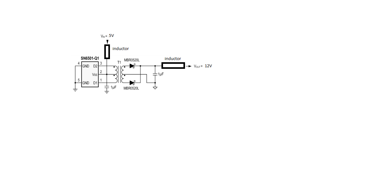
    sorry for late reply & thank you for your support, right now we are using SN6501 with capacitive load of 990uF, but we are using 220uH inductance at the output and 3.3uH inductance to the input(VCC), i wanted to know this might reduce the inrush current of the driver.
  • Hello Kaverappa,

    No problem at all! Are these inductances discrete components? Where are they placed? With a capacitive load like 990uF inrush current may need to be carefully monitored despite the inductors. Is your schematic being finalized or are you able to test this system on a bench?


    Thank you,
    Manuel Chavez

  • Hi Manuel Chavez,

                                            yes we are able to test this system, this inductors are placed as shown in below figure, i want to know does it has any effect inrush current, can we use this driver ic like this.

    i think this inductor might reduce the inrush current, so can i continue with this IC (sn6501) or should i switch to sn6505? 

  • Hi Kaverappa,

    Please excuse my long delay in responding, I wanted this response this to be thorough and correct.

    In short, yes, the addition of inductors will reduce inrush current peaks so that the SN6501 can operate within recommended conditions. However, the exact inductance necessary is being investigated in the lab and data collected is trending towards a higher inductance on the primary supply being more effective. If you allow me until the middle of next week, I can follow up with a concrete conclusion.

    A trade off to inductance on the supply line is the introduced voltage kickback - is that acceptable in this case?


    Thank you for your time,
    Manuel Chavez
  • Hi Kaverappa,

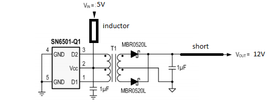
    Although the exact inductance value to reduce current peaks to the acceptable 350mA (in Vcc = 5V operation) for SN6501 varies by system, we've found that using an inductor on the supply line, as shown below, is most effective in reducing inrush current peaks. Please note that high inductances may introduce voltage kickback and distort D1 and D2.


    You can experiment with different values, but about a 200uH inductor will be a good starting point.

    Please respond to this post with comments or thoughts. It has been a while since your last reply, so this thread will be closed out next week if it isn't active.


    Thank you for choosing TI,

    Manuel Chavez