This thread has been locked.

If you have a related question, please click the "Ask a related question" button in the top right corner. The newly created question will be automatically linked to this question.

ISO1042-Q1: Ground design

Part Number: ISO1042-Q1
Other Parts Discussed in Thread: ISO1042, SN6505B

Hi,TI Engineers.

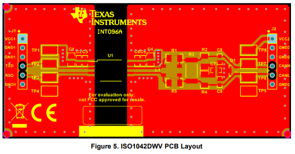
ISO1042-Q1 has two kinds of GND :Digitial GND and Isolate GND. I want to know wthether the two kinds GND plane should connect by a 0 ohm resistor or a capacitor. Or I need to leave these two kinds GND plane  isolate  throughly ? 

Thank you.

Regards.

Gavin Zhang

  • Hi Gavin, 

    The GNDs should remain not-connected in order to preserve the isolation barrier. Any connection between the GNDs would bypass the isolation barrier, and so you would not see any benefits of using an isolated CAN transceiver. So do not place a 0 ohm resistor across the isolator. A capacitor across the isolation barrier is not necessary either. 

    Furthermore, you need to ensure that the GND layers are kept separate on your PCB. 

    You can see an example of a layout for ISO1042 in our EVM user guide. 

    On a similar topic, how are you planning on powering each side of the ISO1042? The power on each side needs to be isolated as well. I would recommend looking at the transformer driver SN6505B for isolated power. Here's an application note on how to isolate signal and power in isolated CAN systems

    Let me know if you have any questions!

    Best regards, 

    Dan

  • Hi,Dan

    Thanks very much for your support.

    Digital-side power voltage is 1.8V and Transeiver-side powervoltage is 5V,and they will be  isolated. Thanks for your reminding.

    Regards 

    Gavin Zhang