Hello,
I would like to ask if I only use 5 input pins of the IC, is the one not used should be pull-low to GND?
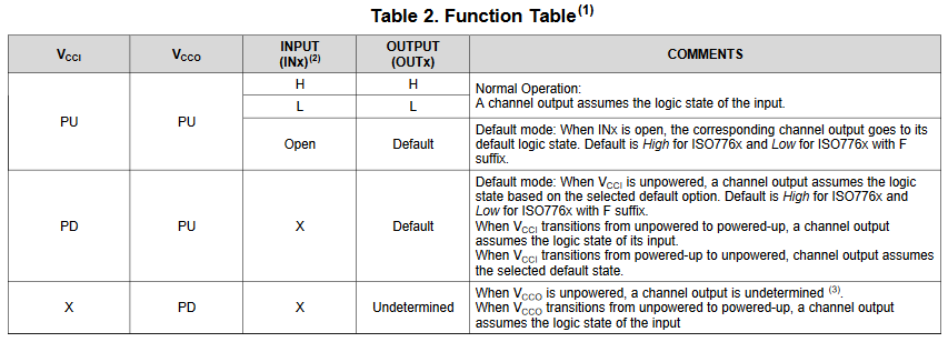
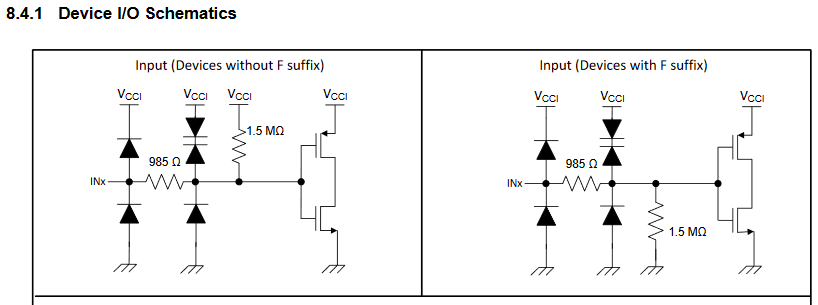
Does this pin can be floating?(Because the IC already has pull-low resistance inside, for example.)
Or if there is any other method of the connection?
Thanks for your replying!
LEE