This thread has been locked.

If you have a related question, please click the "Ask a related question" button in the top right corner. The newly created question will be automatically linked to this question.

SN6505A-Q1: SN6505A/B-Q1 comparison data about efficiency vs load current

Part Number: SN6505A-Q1
Other Parts Discussed in Thread: SN6505A, SN6505B-Q1, , SN6505B

Hello Anant-san,


Could you give me the SN6505A/B-Q1 comparison data about efficiency vs load current, which is tested by using the same trans. but different frequency? 
 
I would like to know these efficiencies @ load current is 10mA to 50mA, when operating frequency is 160kHz and 420kHz.

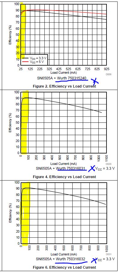
That is, I want to understand SN6505A-Q1’s efficiencies corresponding with Fig.22 (Fig. 22 is SN6505B-Q1’s efficiencies with Wurth 760390014. Fig.2 to Fig.6 are tested with different trans..)


Best regards,
Ochi

  • Hello team, 

    If you don't have the data @ road current is 10mA to 50mA with the same trans. but different frequency, could you tell me the efficiencies @ 10mA to 50mA at 160kHz and 420kHz? 

    I would like to want an enlarged efficiency data @ 10mA to 50mA at 160kHz and 420kHz, if you have it. 

    Best regards, 
    Ochi

  • Hi Ochi-san,

    The team is out for the US Labor Day holiday today, but Manuel from our team will follow-up with you by wed-thu of this week. However, I will post some initial thoughts below.

    Due to the switching frequencies, we generally have to choose a transformer with the appropriate ET product (V-microseconds), which in turn affects the volume of the magnetic core used in the transformer and therefore it’s coupling and efficiency parameters.

    In an ideal situation, if everything else is equal, the lower switching frequencies should have slightly more efficiency due to lower switching losses (which are proportional to frequency). In practice, due to difference in transformer designs, the numbers can vary and we should check it out. If we have to do this comparison on the same transformer, then we have to choose the one with the larger ET product to minimize the risk of transformer saturation.

    Best regards,

    Abhi

  • Hello Abri-san,

    Thnak you. I am looking forward to additional follow up!

    Could you tell me the date about total input current and peak current? I am interested in efficiency @ same trans. but different frequency because I would like to know total input current and peak current.

    Which condition are total input current and peak current reduced?

    Best regards,
    Ochi

  • Hi Ochi-san,

    Thank you for your patience! As Abhi said, all factors constant, we expect a system using the SN6505A to have slightly better efficiency than one using the SN6505B, however this difference can be small and other parameters (like transformer size) could have priority for customers.

    Below are zoomed-in transformer efficiency measurements for your reference. Please note different transformers are used in both measurements and transformers will each have a unique efficiency curve:


    Efficiency curve of PCA transformer measured on SN6505B EVM


    Efficiency curve of Pulse transformer measured on SN6505A EVM

    Transformer input current is not limited by efficiency at different frequencies: transformers have a maximum current rating that typically applies across frequencies. Input current to the transformer is controlled by the transformer driver, and both SN6505A and SN6505B have a 1A current limit to the transformer's primary side. This means up to 1A of current can be input to the transformer, and in normal conditions this current will reflect on the output as a fraction of the turns ratio. Frequency and efficiency do have a small influence here, but turns ratio is the bigger factor.


    Thank you,
    Manuel Chavez

  • Hi Ochi-san,

    Is the information above helpful? Please do let us know.


    Thank you for your time,
    Manuel Chavez

  • Hello Manuel-san,

    Thank you for your supporting!

    Could you tell me how to change the turns ratio? Input voltage and output voltage we will use are defined already. Could I change the turns ratio without changing input and output voltage? If it could do, would you show me what parameters I should change? And then, does the changed parameter affect input peak current? 

    Best regards,
    Ochi

  • Hi Ochi-san,

    You're welcome!

    Turns ratio can be increased or decreased by winding the isolation transformer more or less times, and the necessary turns ratio, N, can be determined by the relationship: N = output voltage / input voltage. This part will be straight-forward since the input and output voltages are already defined. Transformers can then be wound by ratio 1:N where for every turn on the input side, there are N turns on the output side as shown in the graphic below:


    It may be helpful to increase the turns ratio slightly from the calculated value for operating margin over temperature and current loads. In the setup above, the turns ratio can be verified by: Vin x N = Vout. If the output voltage matches or is slightly higher than the output voltage defined, the turns ratio is appropriate.

    Although TI does not manufacture magnetic devices at this time, I can assist with turns ratio calculations and continue to provide general support.

    My apologies, but what is the peak current you referred to? Is this a parameter for continuous operation or during transients?


    I will await your response.


    Thank you for your time,
    Manuel Chavez

  • Hello Manuel-san,

    I referred to peak current for continuous condition, that is, for steady state. And I would like to know how to decease peak input current in steady state.

    You said 'Frequency and efficiency do have a small influence here, but turns ratio is the bigger factor'. Then, I wonder whether I could change turns ratio without changing Vin, Vo, and Io or not.
    Could you tell me whether or not? And also, if I could do that, would you show me which parameters should be changed? Does changed parameter affect input peak current in steady state?

    Best regards,
    Ochi 

  • Hi Ochi-san,

    The peak current for SN6505 is 1A input to the transformer. Many transformers can operate at this current with no problems.

    Changing turns ratio, N, affects Vout with respect to Vin proportionally. If the turns ratio is greater than 1, output voltage will be higher with respect to input voltage. If turns ratio is less than 1, output voltage will be lower with respect to input voltage. Current is affected inversely by this relationship, so if Vout > Vin, Iout < Iin.

    This does not affect the continuous input peak current. Has a turns ratio been determined from the equation in my post above?


    Thank you,
    Manuel Chavez

  • Hello Manuel-san,

    Thank you for supporting us! 

    Best regards, 
    Ochi