This thread has been locked.
If you have a related question, please click the "Ask a related question" button in the top right corner. The newly created question will be automatically linked to this question.
Original question:
ISO3082: ISO3082 application problems
Replies: 4
Views: 632
Part Number: ISO3082
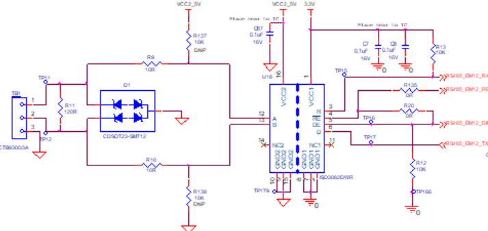
Hello , ISO3082 is a half duplex IC.
My doubt is:
1. If RE is connected to GND, then it is always in receive mode. Now if DE is also high. transmission will happen. Can transmission and receiving happen simultaneously in half duplex? Isn't it supposed to be one by one.
2. Do we need R132, R13 in the circuit ? If yes, why?
3. What is the purpose of R20 and R135? can we eliminate them?
Thank you in advance.
In reply to Tanvi Mahajan1:
Hi Tanvi,
Thanks for asking your question on E2E!
The last attachment you posted didn't seem to load properly on my end. Can you please try to re-post it?
Please see answers to your questions below:
You are correct that TX and RX cannot happen simultaneously as there is only one bus and so there would be a bus collision. You could tie both of these pins as described and handle not transmitting while there is already data on the bus at the software level on the MCU.
Can you re-upload the image? I cannot quite make out which resistors are R132 and R13.
Can you re-upload the image? I cannot quite make out which resistors are R20 and R135.
Please let me know if you continue to have issues uploading the image and I will figure out another way for us to share files.
Best regards,
Dan
In reply to Dan Kisling:
The image is getting distorted after uploading. Let me know your email id .
Thank you.
Thanks for accepting my friend request. I was able to see the schematic better in the private message and have further comments for you. I have highlighted the resistors in question below:
I did not see R132 in the schematic so I'll assume you were inquiring about R12 and R13.
R13 is a pullup resistor for the receiver output pin of the ISO3082. This will pull the net HIGH when the output of R is Hi-Z. See the Receiver Function Table below (which can be found on page 18 of the ISO308x datasheet)
R12 is a pulldown resistor for DE. This wold ensure that the driver is disabled if the net is not driven HIGH by the MCU.
R20 and R135 seemed to be placed to allow you to configure some control behavior for the ISO3082.
If R20 is installed but R135 is not populated, whenever the net is driven HIGH, the ISO3082 will be able to transmit, but not receive. When the net is driven LOW, the ISO3082 will be able to receive, but not transmit. This would cut down on one pin you would have to drive from an MCU, but does not allow you to drive RE and DE separately.
If R20 and R135 are both installed, there are two places to drive the net. RE and DE would be tied together so you would not be able to drive them separately.
If R20 is not installed, R135 must be populated, otherwise there is no way of driving RE. This configuration would allow you to drive RE and DE separately.
A few other notes.
Please let me know if you have any additional questions.