Because of the holidays, TI E2E™ design support forum responses will be delayed from Dec. 25 through Jan. 2. Thank you for your patience.

This thread has been locked.

If you have a related question, please click the "Ask a related question" button in the top right corner. The newly created question will be automatically linked to this question.

ISO1050: ISO1050 hot plug application

Part Number: ISO1050
Other Parts Discussed in Thread: ISO1042

Dear,

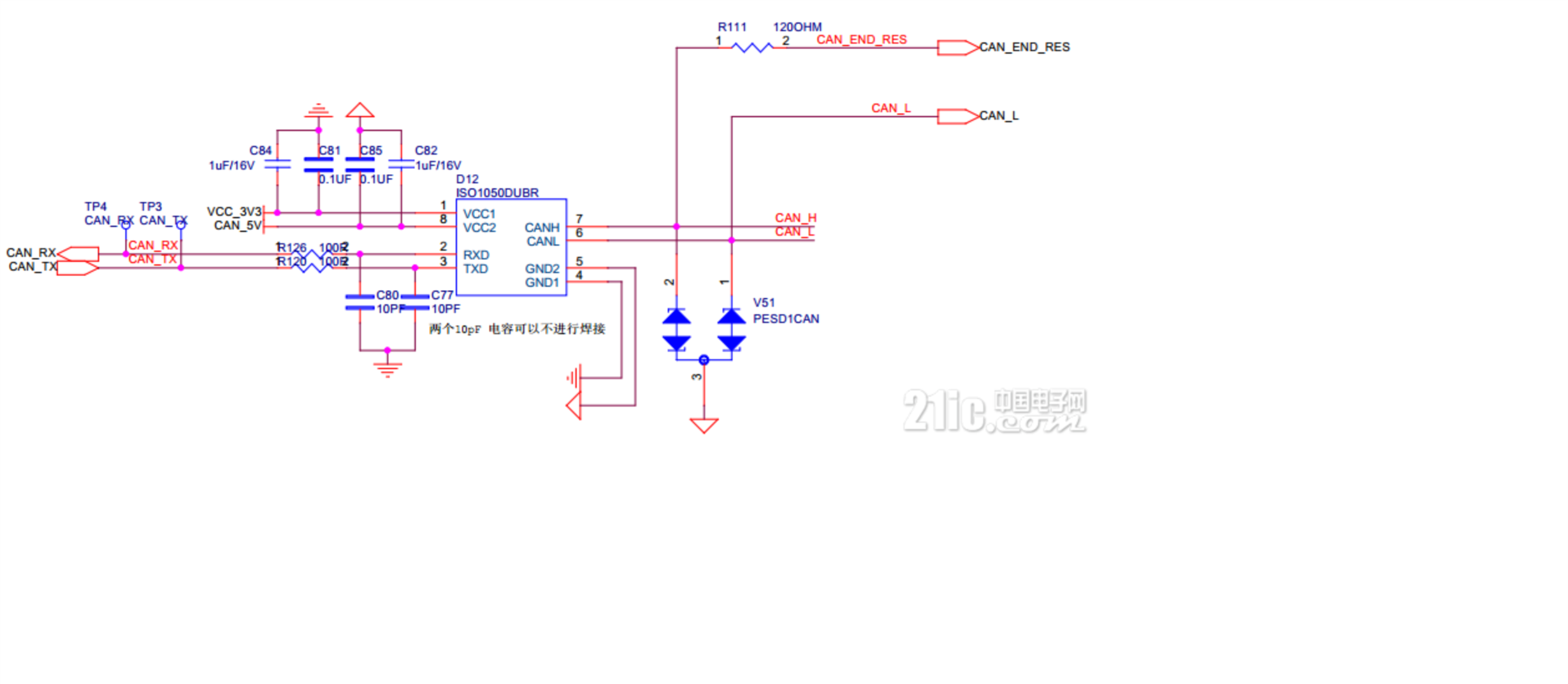
Our customer use ISO1050 for hot plug application, here is the schematic, one DC-DC is used for 24V to 5V, and then convert CAN_5V by isolated module.

He need hot pulg the power line, CANH and CANL during his application, and he found that some ISO1050 are damaged and the power is pulled lower.

There is only one node with the CAN bus. Could you please help to analysis? (Note:PESD1CAN is 24V)

Best regards

Kailyn

  • Hi Kailyn,

    Thank you for your post and for including a schematic of the ISO1050 setup. Which power supply is pulled lower: Vcc1 or Vcc2? Are all of the damaged ISO1050 damaged in the same way or showing the same behavior?

    Please let us know and the team will provide more detailed analysis during normal business hours on Monday.

    Have a great weekend,

    Manuel Chavez

  • Hi Manuel,

    Thank you for your reply, not all ISO1050 are damaged,   the failure is about 5%. And I have confirmed with the customer that the ISO1050 could work normally without hot plug. But his application need hot plug during working.  After damaged, the impedance of CAN_5V is low and it makes the isolation power is pulled lower.

    Do you have any other suggestions?  Thank  you very much.

    Best regards

    Kailyn

  • Hi Kailyn, 

    Thanks for posting on E2E. I have some additional questions and thoughts:

    1. Do you have any pictures of waveforms when the ISO1050 is hot swapped? It would be useful to know what kind of stimulus can be seen at Vcc2, CANH, CANL with respect to GND2. 
    2. PESD1CAN is not the best TVS diode to protect the ISO1050. If you look in the PESD1CAN datasheet, you can see the clamping voltage is 40V for 1A and 70V for 3A, which is outside the abs max range of the ISO1050 (-27 to +40V). I think a better TVS diode with a lower clamping voltage that is inside the abs max range of the ISO1050 would better protect the device. You can read more about how to pick a TVS diode in this application note I wrote: How to Design Isolated CAN Systems With Correct Bus Protection

    3. Since you are also hot swapping Vcc2, we may need a protection diode on this line as well. The waveforms of the hotswap stimulus on Vcc2 will give us a better idea on what kind of device needs to be placed here in order to protect the ISO1050. 
    4. Would your customer be able to upgrade to the ISO1042? It has a higher standoff voltage so it may be able to withstand the hotswap stimulus better. The ISO1042 also has a higher isolation voltage and supports higher data rates. 

    Best regards, 

    Dan

  • Hi Kailyn, 

    I haven't heard from you in a few days. Were you able to determine what was damaging the ISO1050?

    Best regards, 

    Dan

  • Hi Kailyn, 

    I haven't heard from you in over a week so I'm going to close this thread for now. If you need further assistance please feel free to respond to this thread or open a new thread and I would be happy to assist you further. 

    Best regards, 

    Dan

  • Dear Dan,

    Thank you very much. And the customer is changed solution and testing, so he didn't give me feedback about this question.

    Best regards

    Kailyn