This thread has been locked.

If you have a related question, please click the "Ask a related question" button in the top right corner. The newly created question will be automatically linked to this question.

ISO7740: This device can operate at 148 Mbps?

Part Number: ISO7740
Other Parts Discussed in Thread: ISO7640FM, ISO7641FM, TFP410

Hello,

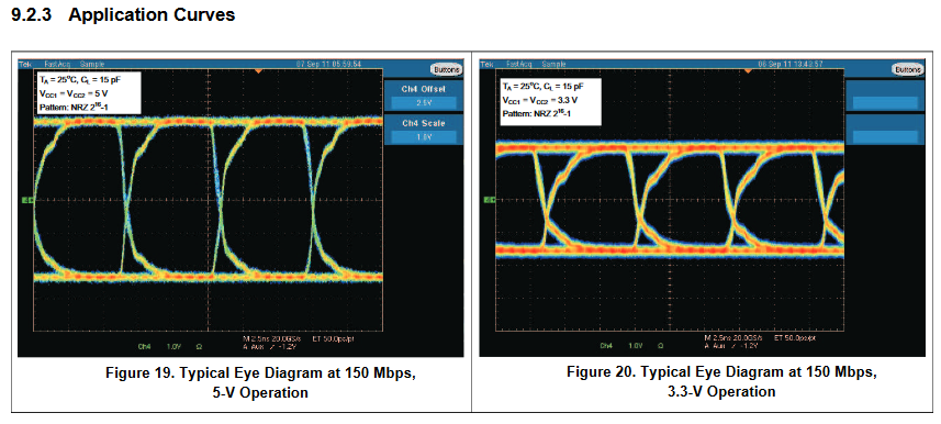
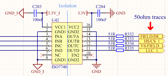
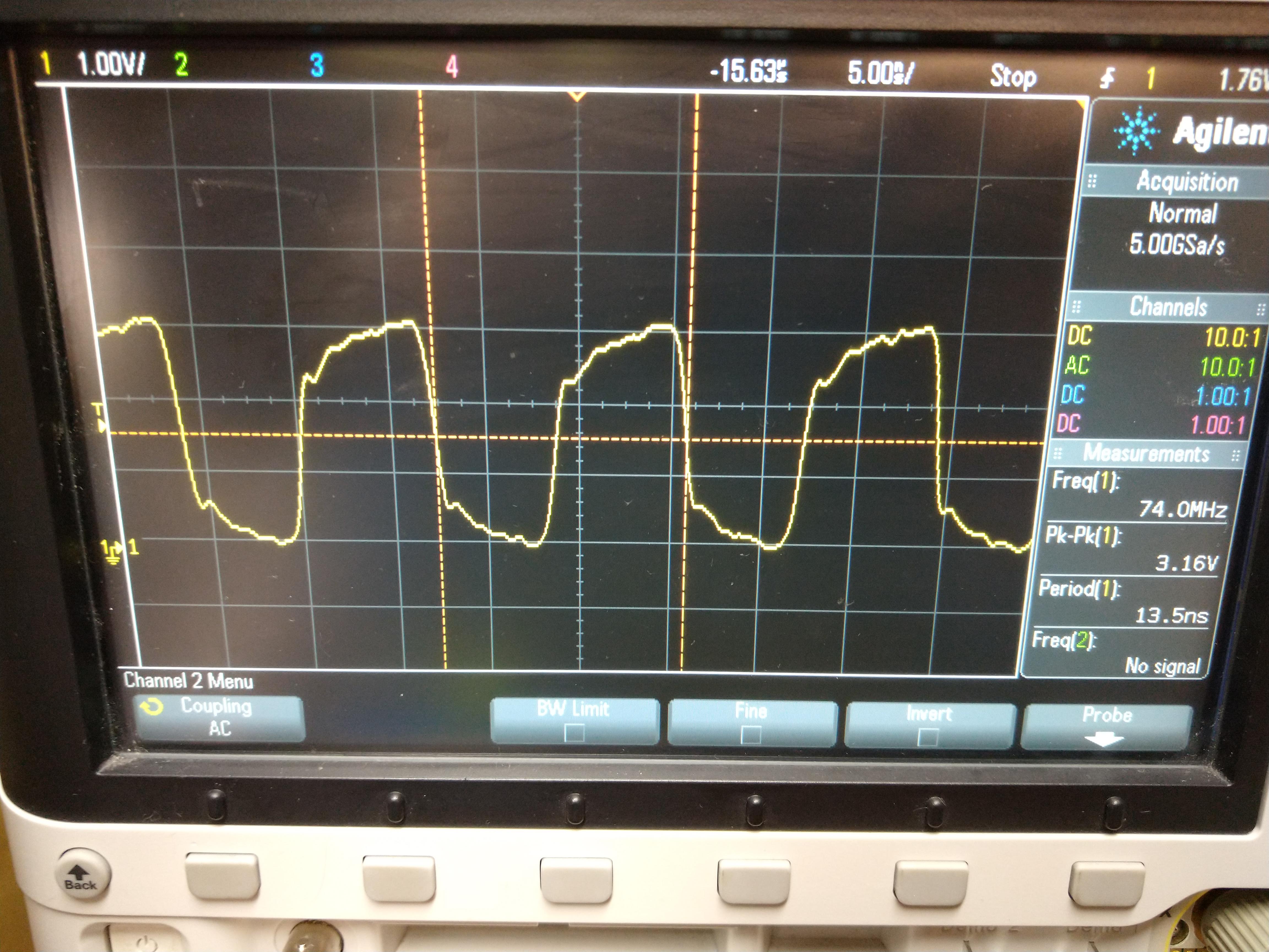
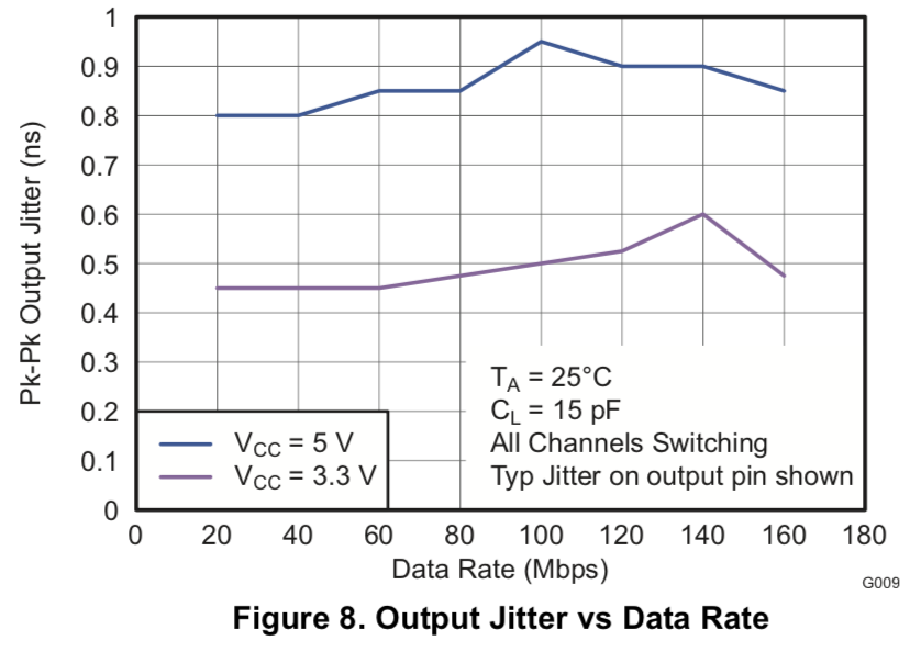
I need to isolate a data bus operating at 148 Mbps in my design. Although the device specification is 100 Mbps, is it possible to achieve the data rate of 148 Mpps without compromising the eye diagram so much?

Thanks in advance,

Rodrigo

  • Hi Rodrigo,

    Thank you for posting, and welcome to E2E!

    Since 148Mbps data transmission rates are outside of the recommended operating conditions for this device, we cannot guarantee that an ISO7740 will perform as expected and the eye diagram will not be compromised more than the datasheet specifies.

    Although it is an older device with lower isolation ratings, ISO7640FM can provide digital signal isolation for data rates up to 150Mbps as shown in its datasheet clippings below:


    Is this device an acceptable alternative for you? Please let us know.


    Thank you,
    Manuel Chavez

  • Hi Manuel, thanks for the answer.

    Please, could you check if the ISO7640FM is pin-to-pin compatible with the ISO7740DWR (this is the PN that I am using in my design)?

    Best regards,

    Rodrigo

  • Hi Rodrigo,

    Yes, ISO7640FM is pin-to-pin compatible with ISO7740DW. Since the two devices belong to different families, they have many differences in performance like isolation voltage, power consumption among others. I would recommend you to go through the datasheet to make sure the device performance is good for your application.

    I would also like to highlight one other difference here that, ISO7640FM has a default LOW state while ISO7740 has a default HIGH state. This can be critical for gate driver application but usually shouldn't be an issue for communication. Please do share your application requirements to understand if the default state is critical for your application. Thanks.

    Regards,
    Koteshwar Rao

  • Hi Koteshwar,

    Please, could you verify the questions below:

    Although the datasheet shows IEC 60.601-1 compliance, it does not mention Medical Equipment in the target applications, as opposed to ISO7740. Can you please confirm if there are any restrictions?

    Do you have any additional information for the projected lifetime?

    Regarding EMC (especially emissions), how does it compare to ISO7740?

    We need to isolate a 24-bit pixel bus at 148Mbps. The data bus operates at 3.3Vdc.

    Thanks,

    Rodrigo

  • Hi Rodrigo,

    Please see my inputs below,

    1. The applications list is not exclusive and exhaustive, the ones listed are only suggestive. Since the digital isolators are very generic, they can be used in most of the applications without any issues. Hence, I do not expect any issues with either ISO7740 or ISO7641FM being used for medical applications.
    2. I know we have not quoted any projected lifetime in the datasheet but it is usually >40 years for isolation barrier.
    3. There is no radiating source in either of the digital isolators and hence, we do not expect either of them to cause any issues for meeting typical emissions standards like CISPR 32.
      1. But do note that the output circuit of the isolator needs to drive the interfaced device which will appear as a capacitive load to isolator. Due to this there will be very small duration peak currents which may show up in the emissions testing. Higher datarate would mean more switching and more such peak currents. One way to address this is use to use a series resistor to limit peak currents without affecting much on your rise and fall times.

    Let me know if you have any questions, thank you.

    Regards,
    Koteshwar Rao

  • Hello Koteshwar,

    Since my last message I had the opportunity to do some measures in the clock line of the data bus of my prototype board that uses the ISO7740.

    The figure below shows how the device is connected in my design. Note that I have the 3.3V_I and GND_I at the isolated side and the 3.3V and GND at the non-isolated side.

    The clock signal that I did the mesures is the LLC_1, connected on the pins 6 and 11 of the device.

    The figure below shows the 74MHz clock signal at pin 6.

    Below is the clock signal at pin 11. Note the jitter in the signal after the device. Nothing changed when we removed the 51R resistor connected at the pin 11.

    Also we had the opprotunity to increase the clock frequency to 148MHz and the jitter got worse.

    I would like to know if you have any thoughts about why I see that jitter, since the frequence of 74MHz is below that the maximum recommended by the device.

    Thank you,

    Rodrigo

  • Hi Rodrigo,

    Thank you for sharing the test waveform. Please do note that 74MHz clock corresponds to a datarate of 148Mbps and this is outside the spec of ISO7740. ISO7740 supports a maximum of 100Mbps datarate uptto which the jitter spec would be in compliance with the datasheet spec. We do not guarantee any jitter spec at 148Mbps for ISO7740 and hence, what you are seeing is could be expected.

    As I stated earlier, ISO7640FM supports 150Mbps operation and has jitter performance data provided in datasheet for 150Mbps (please see the image below). This device is expected to offer better jitter performance compared to ISO7740 at 150Mbps. Please note that the below data is for 25C ambient temperature, it could be worse for other operating temperatures. Thanks.

    Regards,
    Koteshwar Rao

  • Hello Koteshwar, thank you for the answer about the jitter issue.

    We've just tested our prototype regarding EMI and it failed in some frequencies. To help us to understand the failed scenarios, I would like to ask you about the oscillator inside the ISO7740. Do you know which is the operation frequency?

    Thanks is advance,

    Rodrigo

  • Hi Rodrigo,

    Sorry to hear about the issue.
    The internal oscillator frequency is about 450MHz. This is pretty low in its power levels and usually doesn't show up typical industrial emission standards like CISPR 32 Class B. Do you have any RF modules in your system that are getting affected? An RF module like LTE, GSM, Wi-Fi and Bluetooth are very sensitive to radiation to support good wireless communication range and hence those modules can pick-up ISO7740 internal oscillator carrier mildly.

    Please do let us know more details about your emissions testing and share us the results, thanks.

    Regards,
    Koteshwar Rao

  • Hi Koteshwar, thank you for the prompt answer.

    I have another question about EMI. Does ISO7640FM also have this "Emissions Reduction Techniques" implemented in the internal oscillator?

    Best regards,

    Rodrigo

  • Hi Rodrigo,

    ISO7640FM employs an older communication architecture called edge-based architecture. It doesn't require any carrier to be transmitted and hence doesn't have any high frequency carrier that could affect the RF modules. Thus, no emissions reduction technique required either.

    Could you please share us more details related to your emission testing and confirm if you have any RF module in your application? Based on the data you share, I will be able to better support with the issue. Thanks.

    Regards,
    Koteshwar Rao

  • Hi Koteshwar, yes, we have an Wi-Fi module in the design. I'll share the emission testing as soon as we summarizing the data.

    About the ISO7640FM, I've asked you about the emission reduction techniques because of the internal oscillator in the low-frequency channel. Since it has that oscillator, does the emissions in the ISO7640 shouldn't be a problem? By the way, do you know the operation frequency of this oscilator?

    Thanks again,

    Rodrigo

  • Hi Rodrigo,

    Thanks for sharing additional information about having the Wi-Fi module in your system. That explains why you are seeing the emission issue. Please see below the article that talks more about isolators in the presence of an RF module. This article is in reference to OOK isolators (like ISO77xx, ISO78xx) only and the issue is not expected from any other architecture isolators like edge-based architecture of ISO760FM.

    Yes, ISO7640FM has an internal oscillator of about 100kHz and it doesn't have any emissions reduction technique employed because this is low enough frequency for it to affect any of the ISM frequency bands or typical industrial/automotive emissions standards like CISPR 32. We also do not expect ISO7640FM to cause any issues for RF modules.

    Hopefully that makes it clear on why you are seeing your Wi-Fi module is affected. Thanks.

    Regards,
    Koteshwar Rao

  • Hello Koteshwar,

    We are proposing a solution that is to use a higher bandwidth isolator only for the clock signal, and change the ISO7740 to the ISO7640FM for the data bus.

    Do you have a device or any other solution that can operate with the LVCMOS 150MHz clock?

    Thank you!

  • Hello Koteshwar,

    Clarifying our question, the figure below shows our design and the proposed scenario to solve the isolation issue.

    As you know we need to isolate a pixel bus whose the clock operates at 148MHz. Once isolated, the pixel bus is connected to the Texas TFP410 device.

    For the data signals we will use the ISO7640FM and connect them directly to the TFP410.

    For the clock we would like to translate the LVCMOS signal to LVDS, use a 600MHz LVDS isolator, and translates again to LVCMOS connecting it to the TFP410.

    My question is whether you have a solution for the translators (LVCMOS -> LVDS & LVDS -> LVCMOS) respecting the part-to-part skew and jitter of the TFP410? Please, let me know your thoghts.

    Thanks,

    Rodrigo

  • Hi Rodrigo,

    Thank you for further clarifying your question, this helps better.

    This approach should be okay. TI has many non-isolated LVDS transceivers, you could find them at the link below. If you are not able to choose the right part for your application, then I recommend creating a new post on Interface Forum and by using any of the TI LVDS device as reference part number. This makes sure the LVDS team is notified about your post and you get their response quick. Thanks.

    Regards,
    Koteshwar Rao