This thread has been locked.

If you have a related question, please click the "Ask a related question" button in the top right corner. The newly created question will be automatically linked to this question.

ISO1211: ISO1211AC voltage detection threshold level

Part Number: ISO1211

Hi,

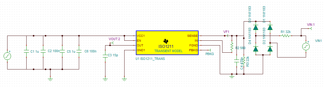
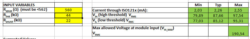
I want to use ISO1211 for ac voltage threshold detection of 120V 60hz mains. I used "ISO121x_Threshold_Calculator_for_9V_to_300V_DC_and_AC_Voltage_Detection" excel file for resistor selection. I choose Rthr=44k and Rshunt=22k for input high voltage threshold of 97.25V.

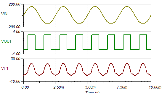
However when I simulate the circuit using TINA, I cannot get output high. Sense node voltage is low.

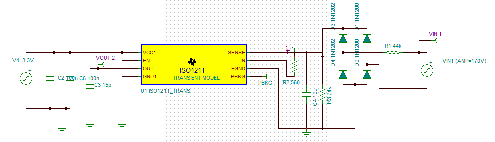
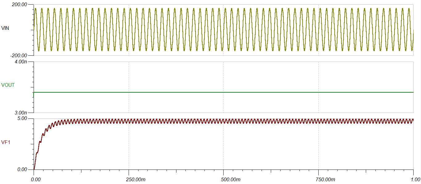
I cannot find the problem on simulation. Anybody can help?

Regards,

Mehmet

  • Hi Mehmet,

    Not sure if this is an issue with the simulation model, please allow us to check on the model and come back to you. Thanks.

    Regards,
    Koteshwar Rao

  • Hi Mehmet,

    I just noticed the VF1 waveform that you have shared, seems like the 10µF input cap is filtering the diode bridge output significantly and maintaining the voltage to <5V. Since the at VF1 is <5V, output is expected to stay LOW.

    Could you please remove the 10µF, change R3 to 24kΩ and test again? Thanks.

    Regards,
    Koteshwar Rao

  • Thank you for answer.

    I simulated the circuit and result is below. If I increase the Cinput, voltage level becoming lower than threshold. I cannot get dc output. What can be the solution for this problem? Thank you.

  • Hi Mehmet,

    As you increase the input cap, the peak value keeps coming down and I believe that is what you are also observing. Large input cap values filter out input signals significantly, is there any particular reason why you would like to use a large input cap?

    We do recommend a cap at input pins to protect against transient waveform like surge or ESD but the values we recommend are in nF. Hence, if you do not have any specific reason for using input caps in µF, we recommend you not to do so.

    Let me know, thanks.

    Regards,
    Koteshwar Rao

  • Hi Koteshwar,

    I want to have pure DC output above threshold voltage. Yes you are right, 10uF is large, now I tried the simulation with 470nF.

    Now the output waveform is almost dc:

    But now I decreased the Rthr resistor value to 32k, and Rshunt to 22k.

    To sum up, I want to have pure DC output with about 97Vrms threshold.

  • Hi Mehmet,

    Thanks for sharing further simulation data. I see you seek to convert the AC input to a clean DC before it is applied to ISO1211. In the existing schematic, the series resistors RTHR limits the charging current to the C4 capacitor and hence the capacitor doesn't reach its expected DC voltage which should be about 108V for 120Vrms/170Vpk.

    One way to achieve that is to reduce the RTHR value so that cap charging current limit is increased but this will increase the voltage appearing at appearing at device SENSE pin and could damage the IC. Hence, a good way to fix this issue is to move the RTHR resistor to after the C4 cap and keep the C4 Cap & diode rectifier together directly connected to input AC voltage. The rectifier and cap filter together first convert AC input to DC and then it should be applied to ISO1211 schematic which includes RTHR and RSENSE resistors.

    This should give you what you are looking. For better filtering, you can further increase the C4 cap and it shouldn't affect ISO1211 operation. Thanks.

    Regards,
    Koteshwar Rao

  • Hi Koteshwar,

    Thank you for answer. I will try your solution. One disadvantage may be C4 capacitor have high voltage rating I guess?

    Regards,

    Mehmet

  • Hi Mehmet,

    Your understanding is correct and this can't be avoided if you would like to convert your AC input to DC before it is applied to ISO1211. Thanks.

    Regards,
    Koteshwar Rao