This thread has been locked.

If you have a related question, please click the "Ask a related question" button in the top right corner. The newly created question will be automatically linked to this question.

ISO1042-Q1: ISO1042BQDWVRQ1 measuring Input cap and differential cap value.

Part Number: ISO1042-Q1
Other Parts Discussed in Thread: ISO1042

Dear Sir,

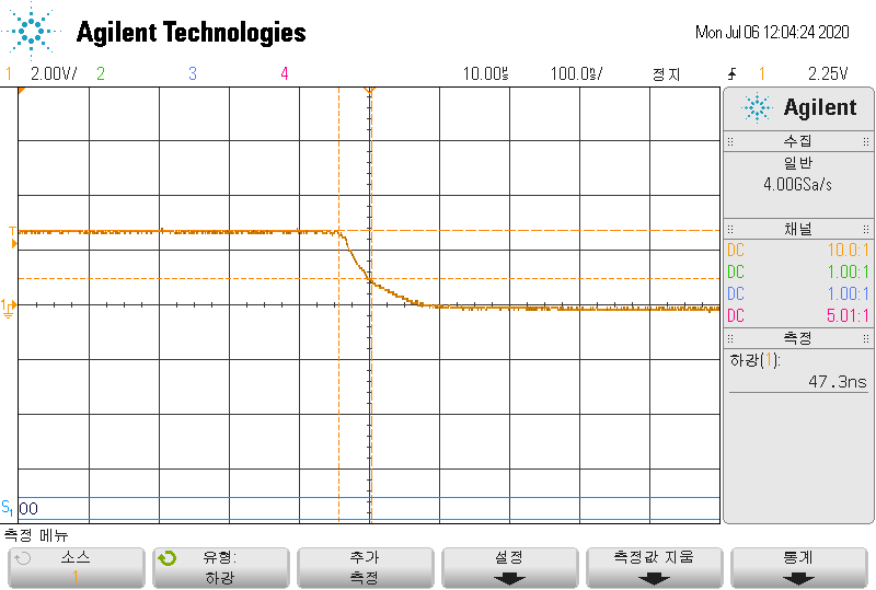
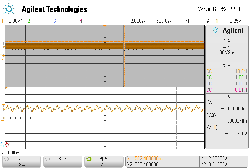
One of my customers use ISO1042BQDWVRQ1 and they want to measure Input Cap and differential cap value as like below pictures.

as below measuring result is fail for spec.

1. could you advise me actually measuring method of  Input Cap and differential cap value?

2. below measuring method is correct? 

  • Dexter,

    We measure the device's properties independent of any PCB or external components. We measure the device alone with an LCR meter at the CAN bus pins. This gives the most accurate results in measuring the device's characteristics without the variables of stray capacitance from the PCB or other external components. 

    Respectfully,

    Lucas 

  • Dear Lucas,

    Of course i did as you said.

    The Results were the same.

    I would to give me the passed test result and test environment.

    Respectfully,

    jun,

  • Dear SIr,

    This method is ISO 11989-2 standard.

    They had measure the device alone with this method. the result is same.

    Could you give me the passed test result and test environment.

    Thanks.

  • Dexter,

    There a couple of key points here in measuring the output capacitance of our device.

    As of 12-15-2016, the ISO 11898-2 standard removed the capacitance measurements. We still meet the older 2015 version of this standard when measured at higher frequencies.

    The output capacitance is frequency dependent. At lower frequencies the capacitance rises. At higher frequencies it goes down. It appears that the customer is measuring at 1kHz which is far below the typical operating frequency of the ISO1042. The ISO1042 is typically used for CAN communications of 1Mbps to 5Mbps. I recommend measuring the capacitance at 1MHz which would be synonymous with a datarate of 2Mbps. The edge rate also needs to be fast at less than 10ns when measuring the capacitance. 

    Respectfully,

    Lucas

  • Dear Lucas,

    When ISO1042 is Power On, off time is good as like below.

    When ISO1042 is Power Off, off time is delay as like below.

    Could you please advise me this situations? Why it happened it when ISO1042 is Power off status.

    Below is 1MHz.

    Below is 1KHz

  • Hi Dexter,

    We're glad to hear that the results of the powered measurement are looking good. 

    It's interesting to see that the measurement appears different while the device is unpowered. I don't believe this is expected but I'm unsure. I'll be looking into this further on our end this week. In the meantime, could you please help me understand your test setup a bit more?

    1. During the unpowered test, are both sides of ISO1042 unpowered? Or just the transceiver side?

    2. While unpowered, is a powered-off power supply still connected to the test board? Or is the board completely disconnected. 

    3. Please verify that that no other devices or components are connected to the pins during the measurement. (Based on the power test this appears to be the case)

    I will follow up later this week with the information I find out. 

    Regards,
    Eric

  • Dear Sir,

    please check it below comment.

    1. Both powers are OFF, CAN side GND connection

    2. The waveform of both IC unit and board connection are the same

    3. As in No. 2, the board connection and IC unit status are the same.

  • Dear Eric,

    Could you please share any update?

    Thanks.

  • Hi Dexter,

    Thank you for following up on this. Our team is still working on understanding the capacitance differences and conducting lab tests. Please anticipate a more detailed update by tomorrow.


    Best,
    Manuel Chavez

  • Hi Dexter,

    Sorry about the delay on this. The answer to your question is more complex than I first anticipated. In this reply, I'd like to explain what I found about the apparent change in capacitance of ISO1042 when the device is unpowered vs when it is powered while using the described setup. 

    To be specific, the pin capacitance does vary slightly between these two states. We have found that the pin capacitance is less when the device is unpowered, but the amount is not considered significant. To describe why the readings vary greatly using the about measurement process, we need to understand more about the internal workings of the device. 

    A CAN transceiver will bias the bus to an recessive level between Vcc and GND (often Vcc/2) when enabled but not actively driving a dominant. This bias can be provided differently, but it ultimately manifests as a current path to both Vcc and GND. This changes the effective R value in the RC calculations described in your original post. This biasing network changes when the device is disabled (or unpowered) and instead biases the bus to a GND potential. This provides a greater path to GND inside the device, further distorting the R value in the calculation. For this reason, I don't believe that the method above is an accurate representation of the capacitive load that the device will present in an application. 

    Furthermore, I will note that the powered capacitive load will likely be what is presented during real operation. For this reason, our measurements and datasheet specifications reflect the properties of the device in an operational state. 

    I hope this helps to clarify the measurements you were seeing with ISO1042 while unpowered. Let me know if you have any further questions regarding this setup or the device. 

    Regards,
    Eric

  • Hi Dexter,

    I hope Eric's post above resolved your questions. Please feel free to reply if there is additional support we can provide or feel free to create a new thread using the red and yellow buttons in the upper-right corner of this window.


    Thank you,
    Manuel Chavez