This thread has been locked.

If you have a related question, please click the "Ask a related question" button in the top right corner. The newly created question will be automatically linked to this question.

ISO1540: Help needed: design an interface that can deal with Long distance I2C Temperature sensor

Part Number: ISO1540
Other Parts Discussed in Thread: PCA9306, , P82B96, P82B715, TCAN1042H, TCA9517

Hi, for one of my customer i have some of those sensor based on the HTU21 Temperature and Humidity Sensor.

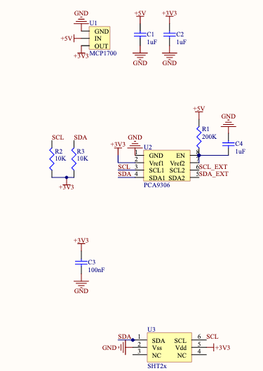
The sensors uses all 4 pairs for power and data, each pair is used for: VCC, GND, SCL and SDA.

Actually those sensors are placed in industrial environment with a lot of noise and they are away 20/25m from the main "controller"...the main controller has many a PCA9306 multiplexed in order to enable the right channel and do the measurement, this works without any issue...and i'm a little bit puzzled...becouse this cable lenght on CAT5e cable originates something like 1600pF of capacitance.

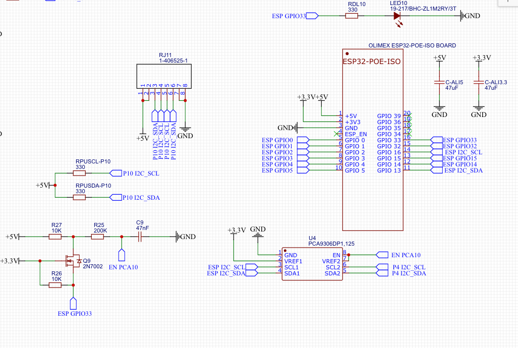
Anyway, i've bought an ESP32POE-ISO from Olimex and wired a breakout board of PCA9306 using 10k resistors pullup on the MCU side and 330ohm resistor on bus side: in my lab environment this solution works, but when i go "away-of-my-bench" in a industrial environment the i cannot read anything.

Really, i don't know what i can do in order to make this work: the "old" gateway has I2C interface identical to the new one, except for the power management: the old one uses a POE PD extraction module (PEM1305 from informart) , the new Olimex ESP32-POE-ISO uses the SI3402 in order to operate power extraction.

You think that placing a ISO1540 on the Bus side of the PCA9306 can help me to solve that issue?

  • Without an isolated power supply, isolating the signals does not make sense.

    I²C was not designed for such cables. You need a stronger buffer like the P82B715 or P82B96.

  • Hi Virt,

    Typical I2C drivers are designed to drive capacitive loads that are presented by PCB traces and other IC pins (I2C specifies max of 400pF for Standard and Fast mode, most devices will struggle to drive loads much beyond this) - such devices will not be able to properly drive long cables. Some non-typical devices such as P82B715 and P82B96 are designed to sink much higher currents and can drive I2C signals over higher capacitive loads and cables. While this will increase the operational distance of the system, it will not substantially improve noise rejection. For particularly noisy environments, it may be worth considering a solution which can translate the I2C signal to a differential signal for transmission on the cable. You can find a reference design that describes how this is possible using the CAN protocol. Switching to transmission over CAN will improve EMI rejection, decrease power usage, and accommodate for ground potential differences between boards. 

    Reference Design for I2C Range Extension: I2C with CAN

    Because it does not appear that power is being isolated in your system, it doesn't seem like this is a requirement for the design. If this is required, isolated CAN transceivers may be used in place of the TCAN1042H's in the reference design along with a method of providing an isolated power supply. 

    Let me know if you have any further questions.

    Regards,
    Eric

  • Many thanks Eric, I really appreciate your answer, I know that I2C it's not intended to work with those specifications, but in my case I have two project constraints that I have to follow:
    - Reuse the old sensors (70+)
    - I don't have to change nothing that it's already installed 
    With those two specifications I don't know what to do...this is very odd: the old gateway works flawlessly, my not...so I've thought that adding some "isolation" will help me to solve this issue, but it seems that this will not help me.
    For completeness, this is the schematic of my interface:
    Nothing special, very simple: nothing more...maybe i'm missing something?
  • So you think that using the Wesp32 over the ESP32-POE-ISO can help me to solve this issue? if i'm not wrong the Wesp32 it's fully IEEE 802.3at compliant...

    Another point using strong buffers like P82B715 or P82B96 is that they needs to be placed both in the MCU side and at Sensor side: i have a constraint that my customer imposed: i don't have to modify nothing a part of the gateway.

    ...there is nothing that i can use only on MCU side?

    Thanks!

  • What's going on with Q9? If you want to disable the PCA9306, pull down the EN pin directly.

    Is the ESP capable of driving the current through those 330 Ω resistors?

    What did the old gateway do with the I²C bus? Maybe is was just using a much lower frequency.

  • Hi Virt,

    Thank you for clarifying the constraints you're working with. If it's necessary for this board to interface with another that expects normal I2C levels, then the previous solutions do not seem ideal. 

    To increase the driving power of the current board without deviating from I2C protocol, I would recommend replacing PCA9306 with an I2C buffer such as TCA9517. PCA9306 is only a level translator and does not re-drive the signal nor does it isolate bus capacitance - thus the ESP32 is currently what is sinking all the current on the cabling. Replacing PCA9306 with a buffer such as TCA9517 (use A-side to drive the cables) will provide some relief to the ESP32 driver and will prevent the stronger 330-ohm pull-up resistors from sourcing current to the highly-loaded side of the buffer. This device also has an enable pin which can be controlled directly from a GPO pin - no 200k-ohm resistor needed. 

    Would you be able to share the differences between your current design and the design that's passing your tests? If needed, this can be shared directly through email if you'd prefer not to post it on the public forum. You can find my email by clicking on my E2E name.

    Either way, let me know if the above suggestion sounds like a more promising solution.

    Regards,
    Eric

  • Thank you Eric, I've already wrote you in order to validate the suggested design and approve it!

    Thanks!

  • Hi Virt App,

    I apologize for the delay; Eric is out of office this week, and I will cover this thread for him meanwhile. I am one of his colleagues on the Isolation team -- please do accept my request to connect and send me a Personal Message with the designs you are considering so we may continue the approval.


    Thank you,
    Manuel Chavez

  • Thanks Manuel,

    I see that you are on the email topic (CC), let's update via email!

    Many thanks!

  • Hi Virt App, all,

    We are continuing this conversation via email and we will post updates and a resolution once we have them.


    Thank you,
    Manuel Chavez

  • Board revisions have been made to use TCA9517 A-side to redrive the signal on the cables. 1.5 k-ohm pull-ups on the cable side appear to meet rise-time requirements for the system with a 27 meter cable. Efforts are being made to further reduce bus capacitance on PCB layout to ensure this requirement continues to be met once fully implemented.

    Currently we are monitoring potential issues due to cross-talk (likely due to long cable), but testing has thus far yielded successful communication. 

    I will close this thread for now but will post an update if other thread-relevant information/solutions are presented in our offline communications. 

    Regards,
    Eric