This thread has been locked.

If you have a related question, please click the "Ask a related question" button in the top right corner. The newly created question will be automatically linked to this question.

ISO7720: Whether or not support isolation two

Part Number: ISO7720
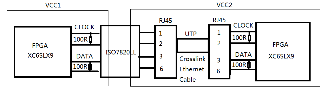
Other Parts Discussed in Thread: ISO7820LL

Through RJ45 and two groups of unshielded twisted pair, we transmit LVDS‘s clock and data。

when use ISO7720LL one time as isolation ship。The frequency of 20Mbps is good,but the frequency of 25Mbps is bad,the bit error rate is very high。  

Is this problem caused by the impedance discontinuity of the cable and PCB ?

As shown in the figure below, when use ISO7720LL two times as isolation ship。No matter how low the frequency is, the bit error rate is very high?

Is this method of two times isolation correct?

  • Hi,

    Thanks for posting your question on E2E and thanks Clemens for your response.

    As Clemens stated, please follow the guidelines when attaching your images.

    In addition, please be sure to include a high level block diagram of your system and the necessary waveforms to debug your problem. Having the LVDS differential waveforms at the near end transmitter, input of the isolator, the output of our isolator and the input of the far end receiver would be helpful to determine the cause of your system bit errors.

    Thanks,

    Dushmantha

  • Hi user5922017,

    I just wanted to check back to see if you are still facing any issues.

    From the above discussion, I understand that you were able to achieve 20Mbps datarate when using one ISO7820LL device while couldn't achieve 25Mbps. When two ISO7820LL devices, you observed high bit error rate irrespective of datarate.

    Please note that it would be necessary to understand your system better and the way you are using isolators to be able to understand the situation better and try debug.
    It is also important to note that LVDS is only a physical layer and the actual implementation or protocol can have significant dependency on the maximum datarate that can be achieved on a physical layer. For example, if you were to use multiple LVDS physical layer channels to achieve SPI communication then your SPI speed would be limited to ~15 MHz. Hence, based on the protocol that you are trying to follow, the actual speed can be quite different. Hence, please do share all the requested information to help you better.

    Since we didn't hear from you in a while, I will go ahead and close this post hoping that you have resolved the issues yourselves. If you are still facing issues, then please respond back with requested information to support you better. Thanks.

    Regards,
    Koteshwar Rao

  • Through clock signal,we serial read data signal.

  • In theory, the ISO7820LL as shown above should work.

    To repeat the earlier request: Having the LVDS differential waveforms at the near end transmitter, input of the isolator, the output of our isolator and the input of the far end receiver would be helpful to determine the cause of your system bit errors.

  • Hi user5922017,

    Please do share more information as requested in earlier posts to be able to debug the issue better, thanks.

    Regards,
    Koteshwar Rao

  • 1、input of the isolator

    2、the output of our isolator

    3、the input of the far end receiver

    4、add 18pF CAP,the input of the far end receiver

  • Hi,

    Thank you for sharing the waveform, appreciate it.
    I see that the data signal that is applied 100Mbps which is the max that ISO7820LL supports. To support this datarate, sufficient care has to be taken to keep the test setup and the input clean.

    Please refer to Figure 22 of ISO7820LL datasheet, also shown below. As indicated in the footnote A, it is important that the input signal source needs to have tr < 3ns and tf < 3ns but in your waveform, this seems to be about 5ns. Hence a better input source meeting this requirement may be needed.
    Please also notice that footnote B refers to output capacitance CP to be <5pF. If you are connecting a twisted pair at the output than it will have significant capacitance and this affects the output waveform. This is why you are seeing a deformed waveform at the output of ISO7820LL. 100Mbps cannot be achieved with twisted pairs loading on the output of ISO7820LL.

    Hence, you may have to either have a low capacitance short length cable or have the two devices connected through PCB on-board with the traces having low capacitance loading. Please note that these conditions are critical to meet 100Mbps.

    Let me know if this clarifies why you are seeing bit error rates at such high speed when ISO7820LL is connected to a twisted pair. Thanks.

    Regards,
    Koteshwar Rao