This thread has been locked.

If you have a related question, please click the "Ask a related question" button in the top right corner. The newly created question will be automatically linked to this question.

ISO7741: Offset voltage on ISO7741

Part Number: ISO7741

Hi,

We are using ISO7741 as SPI isolator. On one side we feed to 3.3v and on the other side we feed to 5.5v. On attached pictures, the measured pin is number 11; which is used as MISO (Master Input, Slave Output) line.

On MISO line we find a voltage level different from 0v or 5v when the line is idle. I MISO line has not any slave connected, however it has 3.05v on 5v side.

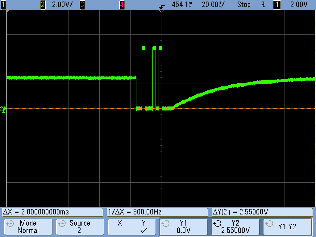
On the next picture," we have 2 slaves connected to pin 11 (MISO line), and the line presents 2.55v.


Is it a normal feature of ISO7741?

Thanks in advance.

  • Hi Juan,

    Thank you for posting, and welcome to E2E!

    Since pin 11 of ISO7741DW is a high-impedance input, it should not be driving the voltage on this pin.Output states for ISO7741 are designed to be only either LOW or HIGH during operation, so a voltage level somewhere in between is not expected.

    Was the top image (yellow waveform) captured without any devices connected to ISO7741? If not, please verify the corresponding output pin (OUTD, pin 6) is following the same state as pin 11 in both HIGH and LOW conditions. This waveform looks to be due to impedances on the node, so using a different oscilloscope probe and testing the device without SPI devices connected may help narrow the root cause.


    Happy Thanksgiving!
    Manuel Chavez

  • Manuel Chavez said:

    Hi Juan,

    Thank you for posting, and welcome to E2E!

    Since pin 11 of ISO7741DW is a high-impedance input, it should not be driving the voltage on this pin.Output states for ISO7741 are designed to be only either LOW or HIGH during operation, so a voltage level somewhere in between is not expected.

    Was the top image (yellow waveform) captured without any devices connected to ISO7741? If not, please verify the corresponding output pin (OUTD, pin 6) is following the same state as pin 11 in both HIGH and LOW conditions. This waveform looks to be due to impedances on the node, so using a different oscilloscope probe and testing the device without SPI devices connected may help narrow the root cause.


    Happy Thanksgiving!
    Manuel Chavez

    Hi Manuel,

    On yellow waveform, pin 11 is unconnected. I'll try to use a different oscilloscope probe, maybe that is the root of the problem.

    Happy Thanksgiving!

    Juan Gomez

  • Hi Juan,

    The device input channels have an internal weak pull-up of 1.5MΩ as shown in the I/O schematics Figure 21 of ISO7741 datasheet. This can happen if the oscilloscope probe used has similar input impedance (~1.87MΩ to produce 3.05V) that forms voltage divider and hence proportionally shows the voltage drop at the input. Using a different probe with higher input impedance should give you close to 5V.

    For the second waveform with 2 slaves connected, the same 1.87MΩ probe when connected in parallel with two floating outputs probably reducing the effecting parallel impedance to 1.3MΩ yielding approximately 2.55V. Using a different probe should produce correct outputs.

    The second waveform also proves that when weakly pulled-up MISO line (pin 11) input is strongly driven by slaves, the voltage levels show up correctly. If you do want to see correct levels even with the existing oscilloscope probe then I would recommend to strongly pull-up MISO line with an external 4.7kΩ pull-up resistor to VCC2. Since the inputs are strongly driven now, it should show correct voltage levels with all oscilloscope probes.

    Please do follow the suggestions provided and let us know the results. I will go ahead and close this E2E post, if you do see any further issue please just reply back with your inputs. Thanks.

    Regards,
    Koteshwar Rao