Hi, expert,
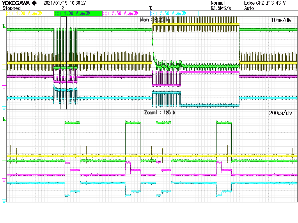
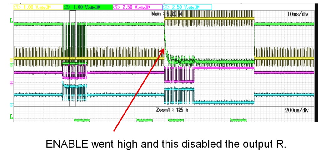
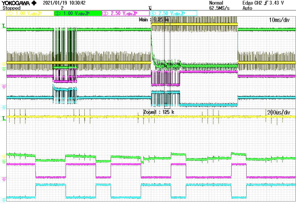
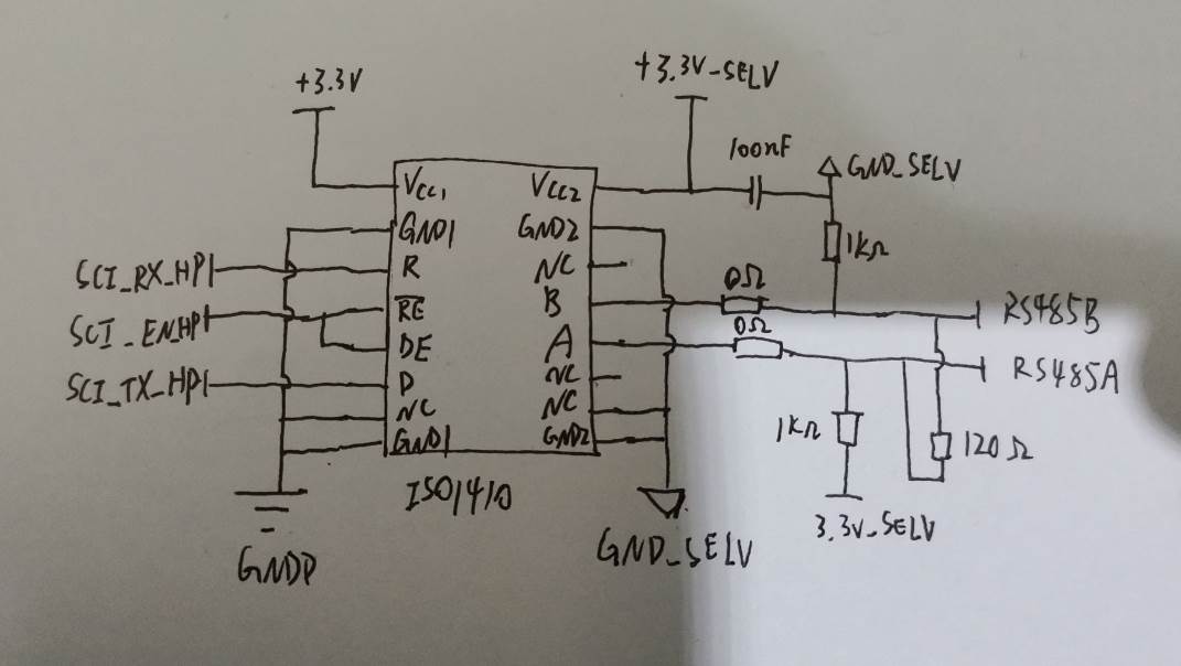
My customer encounters an issue when measure ISO1410 output data, they found the R pin will be pulled down for a short time when use the probe to measure it. Could you please help analysis this issue? Thanks.


Best Regards.
Chen
Hi, expert,
My customer encounters an issue when measure ISO1410 output data, they found the R pin will be pulled down for a short time when use the probe to measure it. Could you please help analysis this issue? Thanks.
Best Regards.
Chen