This thread has been locked.

If you have a related question, please click the "Ask a related question" button in the top right corner. The newly created question will be automatically linked to this question.

ISOW7841EVM: CMC orientation

Part Number: ISOW7841EVM
Other Parts Discussed in Thread: ISOW7841, ISOW7840

Hi,

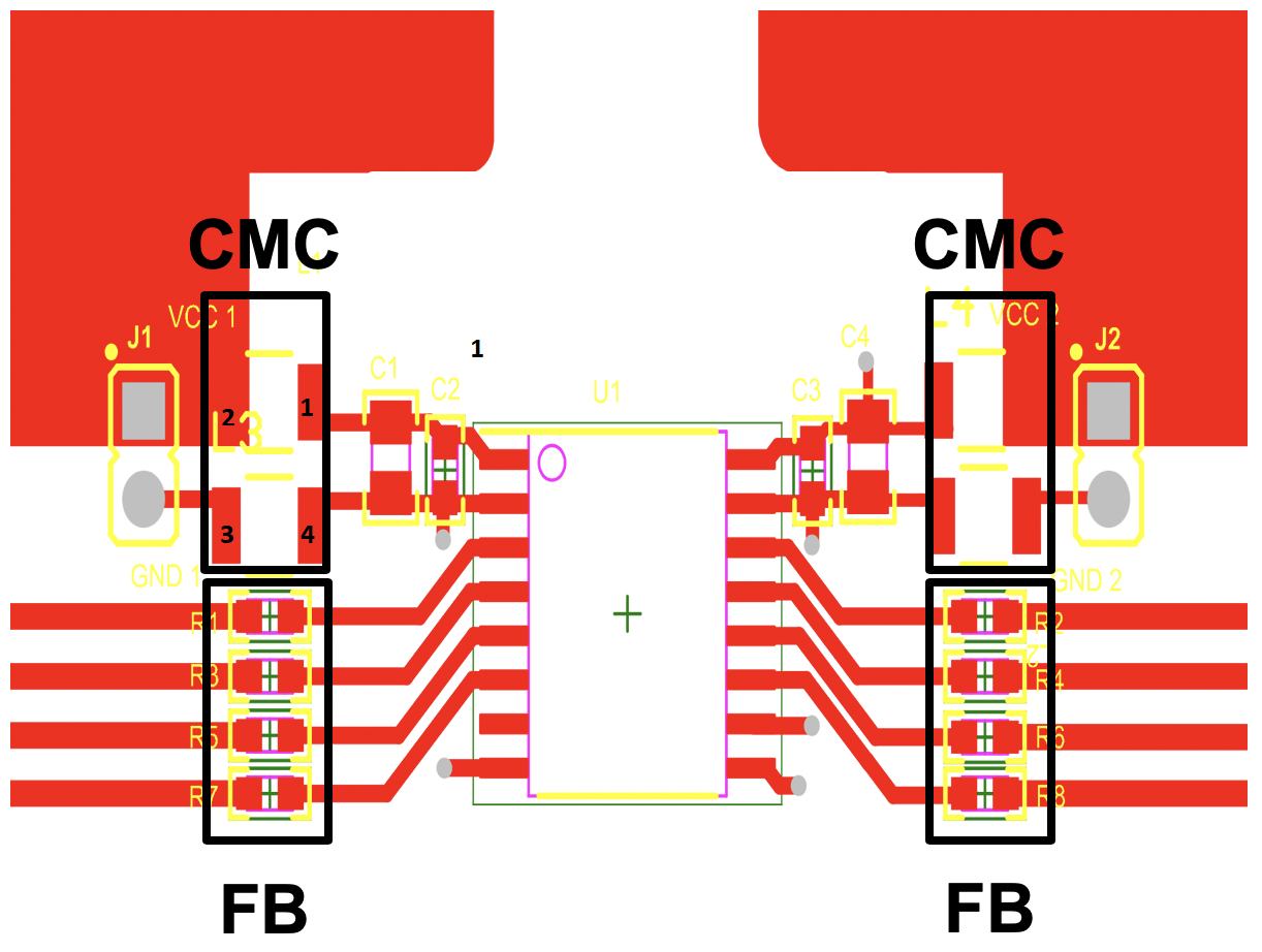
I am planning to use the CMCs as a fallback option in case of EMI issue in my design (which has four ISOW7841, one ISOW7840 and few other DC/DC power supplies (isolated and non-isolated).

Looking at this thread and suggested CMC placement (layout example), and after checking the footprint of the suggested CMCs, I am a bit confused with the CMC orientation/connection - I believe the CMC should be rotated 90 degs (clock wise or anti-clock wise, doesn't matter because there is no polarity).

Could you please clarify?

Thanks,

  • Hi Gorbal, 

    The CMC will allow low frequency signals including DC through with low impedance, but will present high impedance for high frequency signals. In order to reduce emissions it is critical that we reduce any high frequency noise. 

    If I am understanding your question correctly, the CMC would be shorting Vcc to GND if rotated 90 degrees. This would not be good. 

    I believe the placement is correct in the previous thread. 

    Does that help?

    I'm happy to answer any more questions or clarify further. 

    Best regards, 

    Dan

  • Hi Dan,

    Thank you for the prompt reply!

    I do understand why CMC are used and how they work. I've  assumed that the illustrated placement is related to one of the recommended CMCs in which case it does exactly what you pointed at - shortens Vcc to GND - therefore my question (I might be wrong here, either by making wrong assumption about the CMC used as illustration or reading the CMC datasheet wrong).

    Please let me explain my reasoning in more details - I'll use ACT1210 CMC as an example. The data sheet shows the pin assignment as below:

    If we apply this to the placement, the pin numbers would be as

    If I am reading the data sheet correctly and the recommended CMCs are used then it looks to me that Vcc will be shorted to the GND.

    This might show where my confusion comes from - it would be good to know which part is used as well as pin numbering in the illustrations like this!

    Hope this explains my question and suggestion that CMC should be rotated 90 degs.

    Best regards,

    Goran

  • Hi Goran, 

    Thank you for the pictures. I now understand the confusion here. 

    The footprint in the layout is a bit misleading. The pads are larger than necessary. When the board was developed, we wanted to evaluate how ferrite beads would behave in that place as well as CMC. So the pads were extended to allow for either to be populated. Ultimately we decided CMC is the proper part in this place. 

    So the CMC would be oriented as shown in the schematic. 

    Does that clear it up? 

    Best regards, 

    Dan

  • Thanks Dan,

    Yes, all clear now. I have few more questions which I will post in different thread.

    Thanks again,

    Goran